Connector with reinforced shielding shell

A technology of shielding shells and connectors, which is applied in the direction of connection, parts of connection devices, protective grounding/shielding devices of connection parts, etc. Problems such as electromagnetic interference of components and reduced working reliability

Inactive Publication Date: 2012-06-13
SHANGHAI AEROSPACE SCI & IND ELECTRIC APPLIANCE RES INST
View PDF6 Cites 4 Cited by
  • Summary
  • Abstract
  • Description
  • Claims
  • Application Information

AI Technical Summary

Problems solved by technology

[0002] With the continuous improvement of signal transmission rate, the influence of external interference and radiation interference between internal electronic components on the transmission line is becoming more and more obvious. However, in the limited chassis space, the connection between connectors The distance between groups of connectors is very narrow, so how to realize the effective shielding technology of connectors without significantly changing the space volume is a challenge faced by various connector manufacturers at present.
Furthermore, the guide parts of the currently used connectors are usually separated from the connector parts, that is to say, the position accuracy between the connectors is guaranteed by the accuracy of the mounting holes on the PCB board, that is, the printed circuit board, and the electronic control The field of application of the system continues to expand, and the application of the electronic control system is not limited to the static environment. It can be seen that the existing technology is not only unable to resist the electromagnetic interference between its own electronic components, but also increases the difficulty of making the PCB board. It is also difficult to meet the requirements of vibration resistance and shock resistance, resulting in a significant reduction in the reliability of the electronic control system in a dynamic environment

Method used


Image

  • Connector with reinforced shielding shell
  • Connector with reinforced shielding shell
  • Connector with reinforced shielding shell

Examples


Embodiment Construction

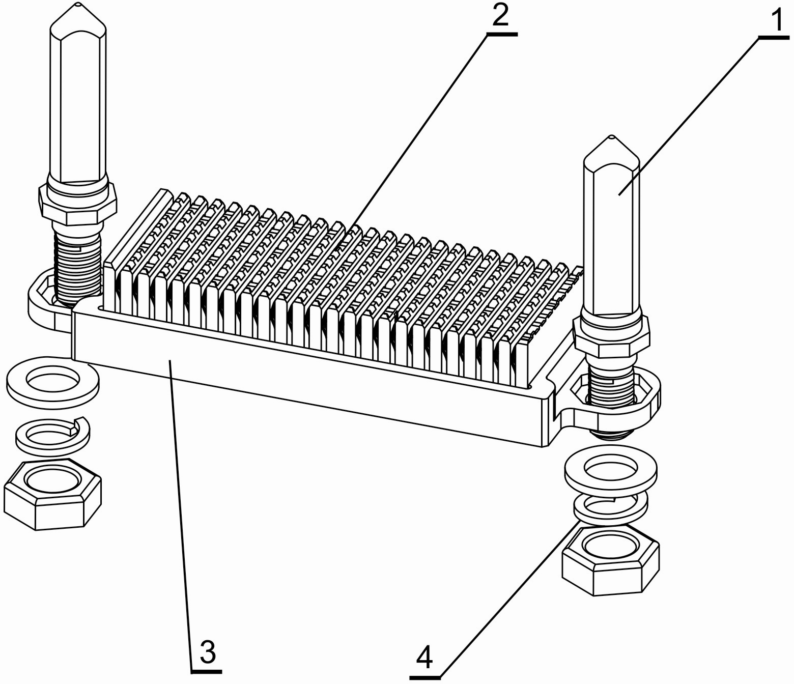
[0015] refer to figure 1 , the present invention includes a guide pin 1, a connector module 2, a housing 3 and a connector 4;

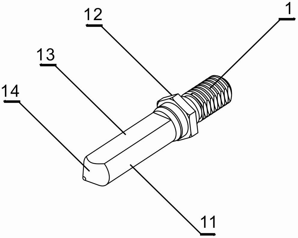
[0016] refer to figure 2 , the guide pin 1 is cylindrical formed by a polished rod 11 and a screw rod, wherein a step 12 is provided between the polished rod 11 and the screw rod, a plane 13 is provided on the cylindrical surface of the polished rod 11, and an arc surface 14 is provided at the end of the polished rod 11;

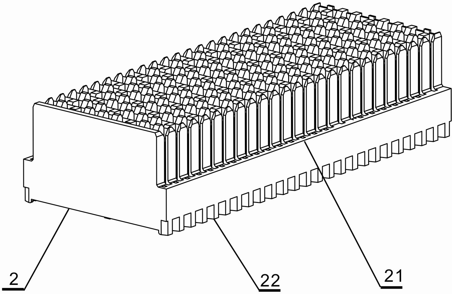
[0017] refer to image 3 , the connector module 2 is a rectangular block, with bosses 21 on both sides, and several grooves 22 parallel to the bottom of the bosses 21;

[0018] refer to Figure 4 , the housing 3 is a rectangular shape surrounded by four side walls, the upper edge of the symmetrical side walls is provided with ribs 31, the lower edge is provided with a row of convex hulls 32, and the outer ends of the remaining symmetrical side walls are provided with connecting The lifting lug 33 is provided with a step hole 34...


PUM


Abstract

The invention discloses a connector provided with a reinforced shielding shell. The connector comprises a guide pin, a connector module, a shell and a connecting piece. The guide pin is provided with steps; the connector module is provided with a lug boss and a groove; the shell is provided with a convex rib, a convex hull, a lifting lug and step holes; the connector module is inserted in the shell; the lug boss is clamped with the convex rib of the shell; the groove is contacted with the convex hull of the shell; the screw rod end of the guide pin permeates into the step holes of the shell; and the steps of the guide pin are matched with the step holes and are fastened by connecting pieces. According to the connector provided with the reinforced shielding shell, the shell is arranged outside the connector module and is positioned and fixed by the guide pin. Therefore, the connector module is connected exactly, steadily and reliably and has a shielding function. The connector provided with the reinforced shielding shell, disclosed by the invention, is mainly applied to an electromagnetic interference sensitive environment and to the electric control system having relatively high requirements on vibration resistance and impact resistance.

Description

technical field [0001] The invention relates to the technical field of electrical connectors, in particular to a connector provided with a reinforced shielding shell. Background technique [0002] With the continuous improvement of signal transmission rate, the influence of external interference and radiation interference between internal electronic components on the transmission line is becoming more and more obvious. However, in the limited chassis space, the connection between connectors The distance between groups of connectors is very narrow, so how to realize the effective shielding technology of connectors without significantly changing the space volume is a challenge faced by various connector manufacturers at present. Furthermore, the guide parts of the currently used connectors are usually separated from the connector parts, that is to say, the position accuracy between the connectors is guaranteed by the accuracy of the mounting holes on the PCB board, that is, th...

Claims


Application Information

Patent Timeline
IPC IPC(8): H01R13/648H01R13/516H01R13/533
Inventor 曹永泉肖顺群
Owner SHANGHAI AEROSPACE SCI & IND ELECTRIC APPLIANCE RES INST
Why Eureka
Try Eureka