Digital intelligent slip ring

An intelligent, slip ring technology, applied in current collectors, electrical components, transmission systems, etc., can solve problems such as high cost, complex structure, and low reliability, and achieve the effect of reducing maintenance, cumbersome maintenance, and improving reliability

Active Publication Date: 2013-07-03
HEBEI HANGUANG HEAVY IND
View PDF8 Cites 0 Cited by
  • Summary
  • Abstract
  • Description
  • Claims
  • Application Information

AI Technical Summary

Problems solved by technology

[0002] At present, most of the existing types of slip rings are invented by means of contact or indirect contact transmission data. At present, the disadvantages of slip rings are low reliability, complex structure, high cost, and must rely on very good benign conductive precious metals to craft

Method used


Image

  • Digital intelligent slip ring

Examples


Embodiment Construction

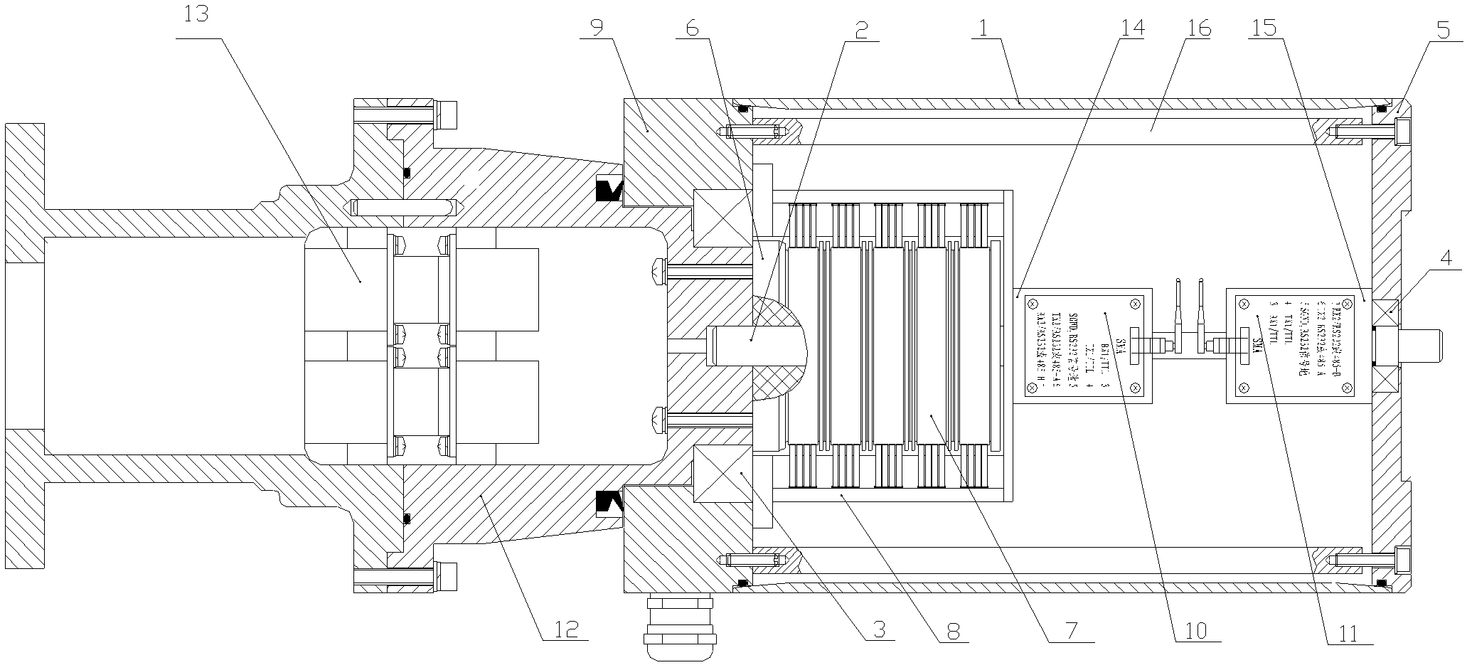
[0008] As shown in the drawings, the stator seat 9 fixes the rotor seat 12 through the bearing 3, and the electrical connector 13 is fixed inside the rotor seat 12. The left end of the rotating shaft 2 is fixed on the rotor seat 12 at the center of the bearing 3, and the right end of the rotating shaft 2 passes through the bearing. 4 is fixed with the end cover 5, and the end cover 5 and the stator seat 9 are fixedly connected by a tie rod 16, and the outer end cover 5 of the tie rod 16 and the stator seat 9 are sealed and fixed to the shell 1.

[0009] On the left side of the rotating shaft 2, an insulating annular column 6 is fixed, and a conductive ring 7 is fixed on the annular column 6, and the brush group 8 slidingly matched with the conductive ring 7 is fixed with the stator base 9.

[0010] The wireless rotary communication module 10 is fixed on the right side of the rotating shaft 2, the communication line of the wireless rotary communication module 10 is drawn through...


PUM


Abstract

The invention relates to a slip ring which can achieve electric energy or electric signal transmission in 360-degree rotation mode. A stator seat fixes a rotor seat through a bearing, an electric connector is fixed in the rotor seat, the left end of a rotating shaft is fixed on the rotor seat at the center of the bearing, the right end of the rotating shaft is fixed with an end cover through a bearing, and a casing is fixed between the end cover and the stator seat in sealing mode. An insulated annular column is fixed on the left side of the rotating shaft, an electric conductive ring is fixed on the annular column, and an electric brush group matched with the electric conductive ring in sliding mode is fixed with the stator seat. A wireless rotation communication module is fixed on the right side of the rotating shaft, a communication line of the wireless rotation communication module is extracted through the electric connector, a wireless stationary communication module is fixed on the end cover close to the right side of the rotating shaft, and a communication line of the wireless stationary communication module is extracted through a stuffing box on the stator seat. The digital intelligent slip ring is small in contact consumption, convenient to maintain, simple in structure and low in cost.

Description

technical field [0001] The invention relates to a slip ring, which can realize 360-degree rotation and transmit electric energy or electric signal. Background technique [0002] At present, most of the existing types of slip rings are invented by contact or indirect contact transmission data. The current disadvantages of slip rings are low reliability, complex structure, high cost, and must rely on very good Good conductive precious metal to craft. The extraction and use of precious metals have caused a lot of pollution to the environment. Precious metals are non-renewable resources, and they also play a certain role in slowing down the excessive consumption of such resources. Contents of the invention [0003] In order to overcome the disadvantages of the prior art, the present invention relates to a digital intelligent slip ring, which has low contact consumption, convenient maintenance, simple structure and low cost. [0004] The technical solution adopted by the pres...

Claims


Application Information

Patent Timeline
Patent Type & Authority Patents(China)
IPC IPC(8): H01R39/08H04B1/38
Inventor 王连生李伟明郝建刚杜玉娟姜晓亮
Owner HEBEI HANGUANG HEAVY IND
Why Eureka
Try Eureka