
Head plug-in mechanism for vertical plug-in machine

A plug-in machine and plug-in head technology, applied in the direction of electrical components, electrical components, etc., can solve the problems of slow running speed, difficulty in satisfying plug-in processing, and low processing efficiency, so as to improve response speed, prolong practical life, and reduce friction Effect

Active Publication Date: 2012-06-13
海宁经开产业园区开发建设有限公司
View PDF4 Cites 4 Cited by
  • Summary
  • Abstract
  • Description
  • Claims
  • Application Information

AI Technical Summary

Problems solved by technology

[0003] During the insertion process of vertical electronic components, the vertical component is generally clamped to the top of the PCB circuit board by the component fixture, and then the pressing device moves down until the vertical component is pressed into the PCB circuit board, But in the actual insertion process, when the component fixture and the pressing device move down synchronously until the pins of the vertical component are embedded on the PCB circuit board, the component fixture needs to be retracted from the side, otherwise it is easy to lose the inserted The vertical components are brought up, which affects the normal insertion of the plug-in machine
[0004] In this regard, a plug-in head mechanism has appeared on the market. When the component fixture is retracted, it first withdraws from the side and then retracts upward. This technical solution is difficult to meet the requirements of plug-in processing due to its complex structure, slow running speed, and low processing efficiency. needs, deficiencies

Method used


Image

  • Head plug-in mechanism for vertical plug-in machine
  • Head plug-in mechanism for vertical plug-in machine
  • Head plug-in mechanism for vertical plug-in machine

Examples


Embodiment Construction

[0028] In order to facilitate the understanding of those skilled in the art, the present invention will be further described below in conjunction with the embodiments and accompanying drawings, and the contents mentioned in the embodiments are not intended to limit the present invention.

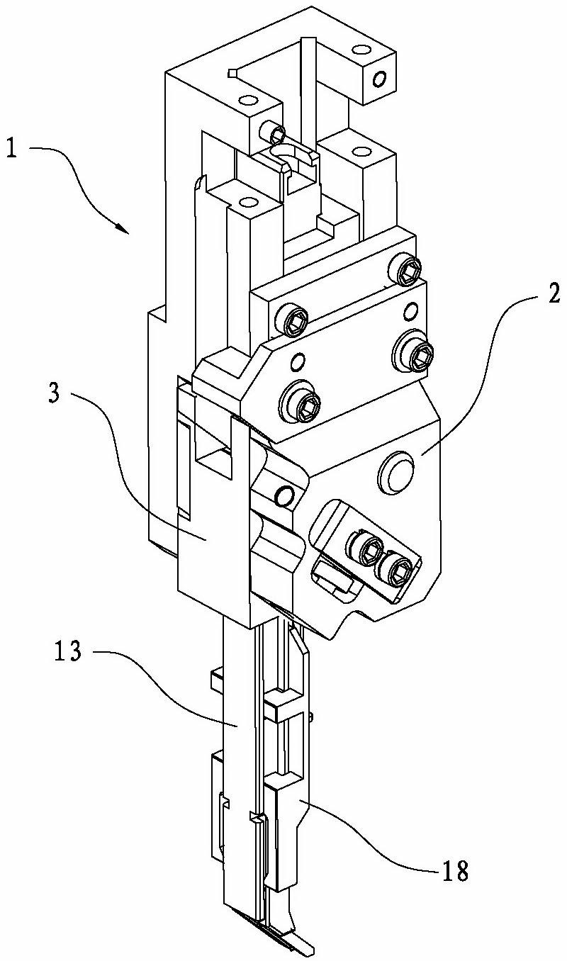
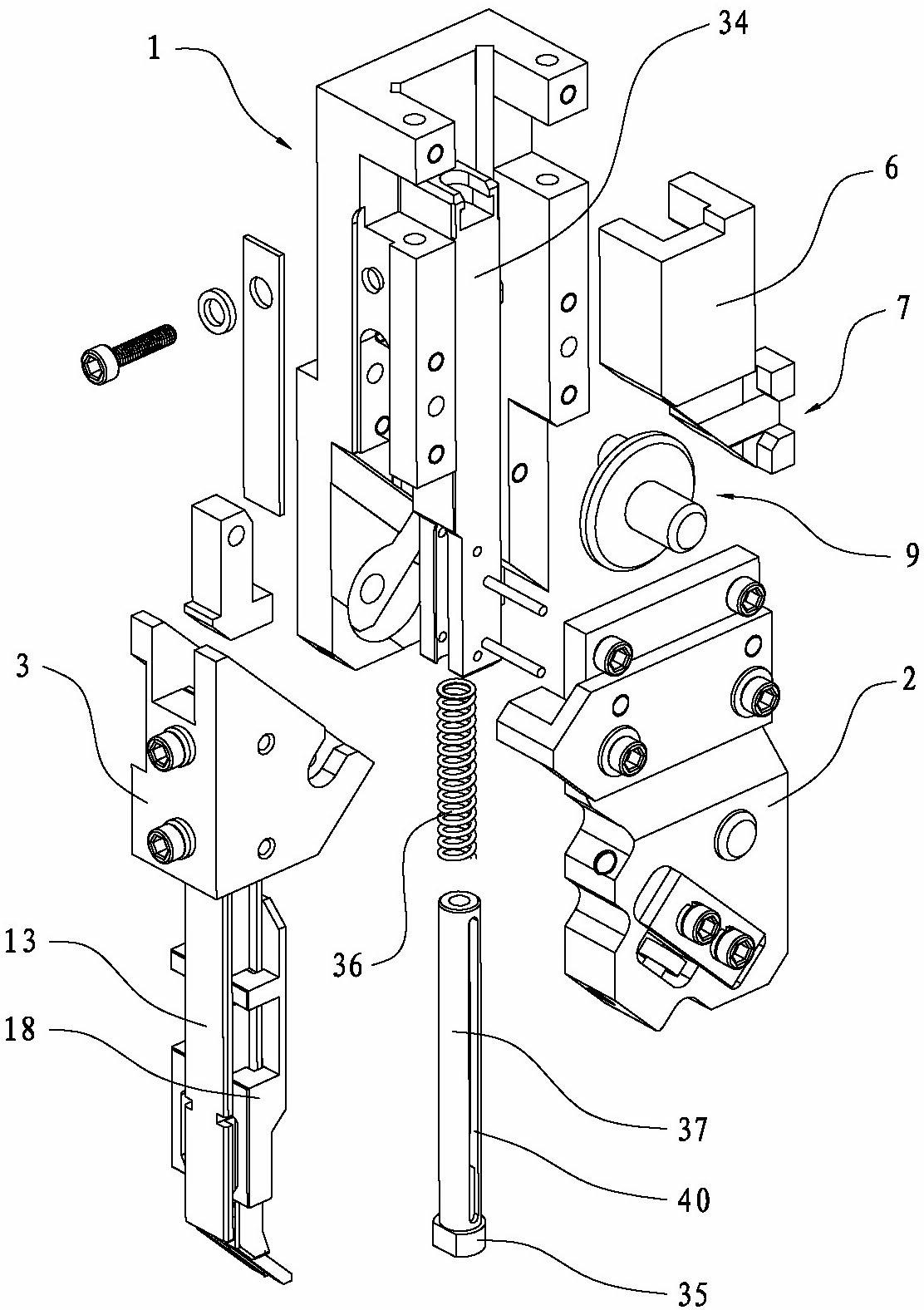
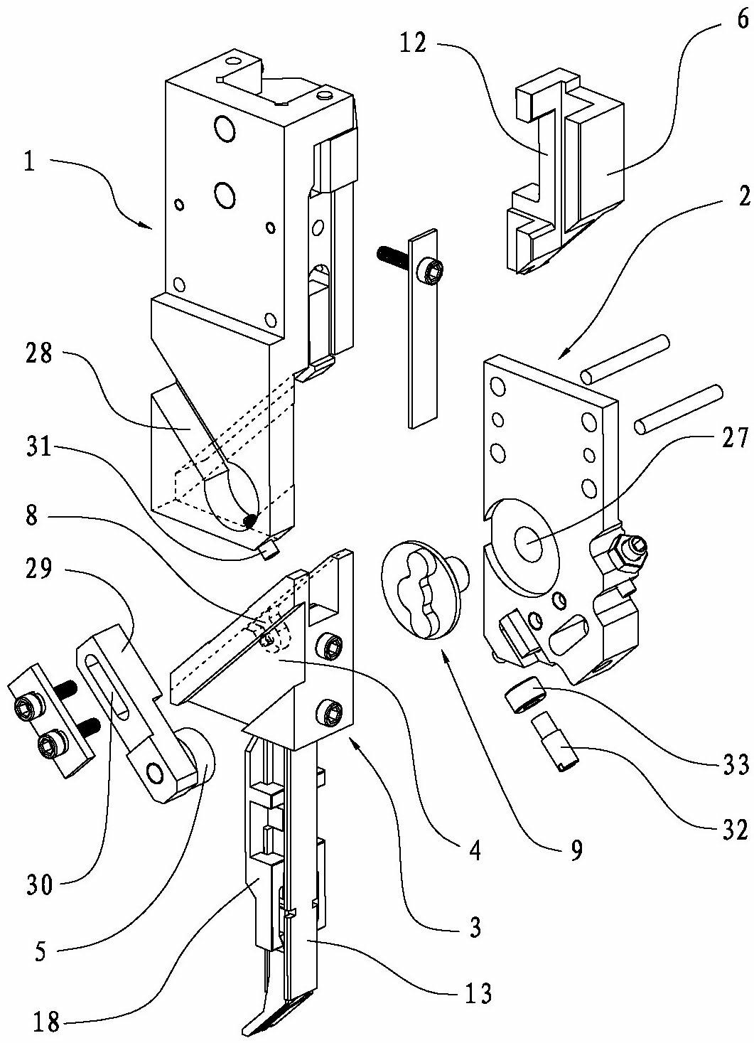
[0029] Such as Figure 1 to Figure 11 As shown, a plug-in mechanism at the head of a vertical plug-in machine includes a plug-in head body 1, a component fixture, a rear cover 2, and a triangular slider 3 movably arranged on the plug-in head body 1, and the component fixture is installed on the triangular slider 3 , the rear cover 2 is arranged on the rear side of the plug-in head body 1, and it is characterized in that: the triangular slider 3 is provided with an inclined chute 4, and the plug-in head body 1 is equipped with a first bearing 5, and the first bearing 5 is movably embedded in the inclined chute 4; the plug head body 1 is equipped with a pressing device and a driving block 6 th...


PUM


Abstract

The invention relates to technical field of vertical plug-in machine equipment, in particular to a head plug-in mechanism for a vertical plug-in machine. The head plug-in mechanism comprises a plug-in head body, an element fixture, a back cover and a triangular slide block, wherein a pressure device and a driving block capable of moving upwards and downwards are arranged on the plug-in head body; the driving block is provided with a first gap groove; the triangular slide block is provided with a linkage groove; the back cover is provided with a linkage rotating block; the linkage rotating block is provided with two bump parts; a projecting linkage bump is arranged on the pressure device; the driving block is provided with a second gap groove; a linkage bump is embedded into the second gap groove; and oblique movement of the triangular slide block, the opening and clamping of the element fixture and downward insertion action of the pressure device are controlled simultaneously during upward and downward movement of the driving block, so that the opening of the element fixture and the downward insertion action of the pressure mechanism are kept consistent accurately, and the accident of pressing damage or falling of a vertical element is prevented effectively. The head plug-in mechanism has a simple structure and high stability.

Description

technical field [0001] The invention relates to the technical field of vertical plug-in machine equipment, in particular to a plug-in mechanism at the head of a vertical plug-in machine. Background technique [0002] With the rapid development of electronic technology, the use of electronic products is becoming more and more extensive. PCB circuit boards are important components of electronic products. Vertical plug-in machines are processing equipment that insert various vertical components into designated positions on PCB circuit boards. . In the processing process of the vertical plug-in machine, the components with vertical components are generally conveyed to the station device for material distribution, and then embedded in the chain clip, and then transported by other devices to the The upper part of the PCB board is positioned, and then the clamping device moves down, and the vertical component is accurately inserted into the preset pin socket of the PCB circuit boa...

Claims


Application Information

Patent Timeline
IPC IPC(8): H05K13/04
Inventor 王媛秀李杨寿曾翔清钟承文陈卓标
Owner 海宁经开产业园区开发建设有限公司
Learn More