Cylindrical roll bearing solid retainer stamp assembling mould

A technology of cylindrical roller bearing and solid cage, applied in the direction of bearing components, shafts and bearings, forming tools, etc., to achieve the effect of stable operation and beautiful embossed shape

Inactive Publication Date: 2012-06-20
WAFANGDIAN BEARING GRP CO LTD
View PDF6 Cites 8 Cited by
  • Summary
  • Abstract
  • Description
  • Claims
  • Application Information

AI Technical Summary

Problems solved by technology

[0002] The solid cage of cylindrical roller bearings is to separate the rolling elements at equal distances and evenly distribute them on the circumference of the raceway to prevent the rolling elements from colliding and rubbing against each other during operation, guide and drive the rolling elements to roll on the correct raceway, and prevent The rolling elements fall off, and the outer diameter of the solid cage of the cylindrical roller bearing does not exist in the current prior art. The embossing assembly technology is used in the processing and stamping process.

Method used


Image

  • Cylindrical roll bearing solid retainer stamp assembling mould
  • Cylindrical roll bearing solid retainer stamp assembling mould
  • Cylindrical roll bearing solid retainer stamp assembling mould

Examples


Embodiment Construction

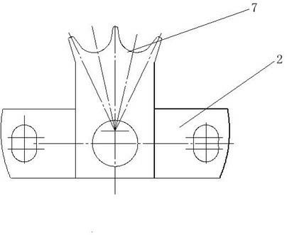
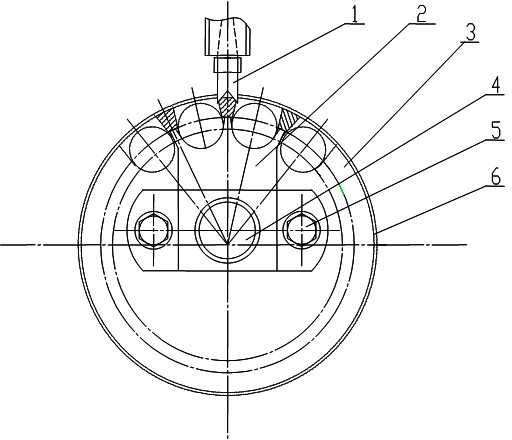
[0017] An embossing assembly mold for a solid cage of a cylindrical roller bearing, which is composed of a punch part 1, a positioning body 2, a bottom plate 3, a pin 4, a screw 5, and a bearing assembly 6; the positioning body 2, pins 4, and screws 5 are all on the bottom plate, the pin 4 is at the center of the bottom plate 3, the screw 5 is located on both sides of the pin 4, the punch part 1 is vertically aligned with the outer diameter of the cage in the bearing assembly 6, and the positioning body has The claw 7, and the claw 7 of the positioning body is in contact with the inner diameter of the cage in the bearing assembly 6.

[0018] Described screw 5 is two.

[0019] The part of the curved surface of the positioning body 2 in contact with the rollers is processed to ensure equal division and make the roughness of the curved surface meet the requirements.

[0020] The tapered surface of the punch part 1 should ensure its angle difference when adding, the sharp corners...


PUM


Abstract

The invention relates to the technical field of new processes and new processing equipment, in particular to a cylindrical roll bearing solid retainer stamp assembling mould, which is provided with a positioner and a punch reasonable in structural designs. During assembling, a retainer is placed on the fixed positioner after rollers are mounted in pockets of the retainer, the punch moves to the outer circumference of the retainer until required stamps are stamped, and then stamps required by the outer circumferences of the other retainers are stamped sequentially. During machining of contact curve surfaces between the positioner and the rollers, the requirement of uniform difference is met, and the requirement for the roughness of the curve surfaces is guaranteed. During machining of the conical surface of the punch, the requirement for angular difference is met, tip angles are chamfered, and the roughness of the conical surface meets the design requirement. Alignment between the punch and the outer circumference of the retainer in a bearing component is guaranteed while a certain distance is reversed between the same, so that the punch is guaranteed to move into the retainer radially to realize stamping effect.

Description

technical field [0001] The invention relates to the technical field of new technology and new technology equipment, in particular, it relates to an embossing assembly mold for a solid cage of a cylindrical roller bearing. Background technique [0002] The solid cage of cylindrical roller bearings is to separate the rolling elements at equal distances and evenly distribute them on the circumference of the raceway to prevent the rolling elements from colliding and rubbing against each other during operation, guide and drive the rolling elements to roll on the correct raceway, and prevent The rolling elements fall off. In the current prior art, there is no imprinting assembly technology for the outer diameter of the solid cage of the cylindrical roller bearing during the stamping process. Contents of the invention [0003] In view of the above technical problems, the purpose of the present invention is to provide a cylindrical roller bearing solid cage imprint assembly mold, ...

Claims


Application Information

Patent Timeline
Patent Type & Authority Applications(China)
IPC IPC(8): B21D37/10B21D43/00B21D53/12
Inventor 周建美李明震姜智姚国栋柳书敏邹德鹏
Owner WAFANGDIAN BEARING GRP CO LTD
Why Eureka
Try Eureka