
Grid marking tool

A scribing tool and grid technology, applied in manufacturing tools, workshop equipment, etc., can solve problems such as rework, inaccurate positioning and scribing, and missing documents, to eliminate scribing errors, accurate and consistent grid lines, and improve work efficiency. The effect of efficiency

Inactive Publication Date: 2012-06-20
何成锋
View PDF7 Cites 1 Cited by
  • Summary
  • Abstract
  • Description
  • Claims
  • Application Information

AI Technical Summary

Problems solved by technology

Due to the different thickness of the marking pen tip, a certain error will be formed when the marking pen tip moves along the edge of the metal ruler. At the same time, there is also an error due to the cooperation between the human eye and the hand, so the divisions and lines drawn are not accurate, which is difficult. Meet the design requirements, because of inaccurate positioning and marking, rework often occurs
The low efficiency and poor quality of scribing also bring a lot of trouble to the follow-up process
[0003] So how can we make the grid and line not be dominated by the above conditions and personnel factors? Therefore, the development of tools dedicated to grid marking is of great significance for improving work efficiency, improving product quality, simplifying operating procedures and improving production efficiency. There is no report on this technical article in the literature

Method used


Image

  • Grid marking tool
  • Grid marking tool
  • Grid marking tool

Examples


Embodiment 1

[0107] Embodiment 1, the dashed line of the equidistant grid line: determine that the grid line interval data is 2.49cm;

[0108] Rotate the angle positioning ruler 3 to the starting angle position;

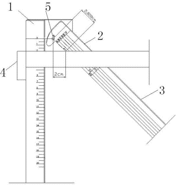
[0109] According to the given grid line interval data of 2.49cm, move the position of the vernier 4 on the standard board ruler 1, so that the upper edge of the horizontal ruler 41 of the moving vernier ruler 4 is aligned with the data scale 2.49cm on the standard board ruler 1;

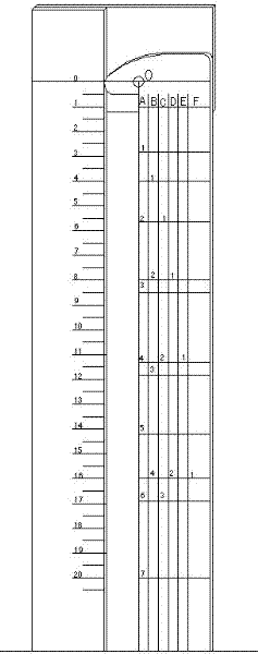
[0110] Observe the position of the line along the horizontal ruler 41 of the compass 4 on the angle positioning ruler 3; virtualize the overlapping line of the upper edge of the horizontal ruler 41 on the angle positioning ruler 3 as a reference line R, observe the location line on the angle positioning ruler 3 scale;

[0111] Lock the position of the vernier 4, take the virtual reference line R on the angle positioning ruler 3 as a reference, and the nearest scale below the reference line...

Embodiment 2

[0115] Embodiment 2, evenly divide the grid in the given line range:

[0116] Rotate the angle positioning ruler 3 to the starting angle position;

[0117] Given that the vertical line range is within 30 cm, the number of divisions is determined to be 10;

[0118] Align the starting point 0 of the standard board ruler 1 with the upper edge of the given vertical line range;

[0119] Move the vernier 4 at the position of the standard board ruler 1; move the upper edge of the horizontal ruler 41 of the movable vernier 4 to 30 cm from the lower edge of the given scribe range;

[0120] Observe the position of the line along the horizontal ruler 41 of the vernier 4 on the angle positioning ruler 3; virtualize the overlapping line of the upper edge of the horizontal ruler 41 on the angle positioning ruler 3 as a reference line R;

[0121] Lock the position of the vernier 4, and then turn the angle positioning ruler 3 counterclockwise until the position line with the nearest ...


PUM


Abstract

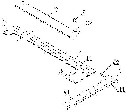
The invention relates to a grid marking tool which is composed of a standard board rule, a back board, an angle set rule and a vernier, wherein the angle set rule is a rule board with a zone identifier; the vernier is a square; the angle set rule is connected to the back board through the match between the axle holes on a hinge pin and the angle set rule and the axle hole on the back board; the angle set rule 3 can rotate by taking the hinge pin 5 as an axle center; and the vernier moves up and down by taking a chute as a track. The grid marking tool provided by the invention realizes accurate marking positioning, eliminates error caused by manual operation, ensures accurate and consistent marked grid lines, and is exclusively used for marking grid lines and uniformly dividing grids in a given marking range; and moreover, the grid marking tool is easy and convenient to operate, greatly improves the working efficiency, product quality and production efficiency, and has creativity and popularization values.

Description

technical field [0001] The invention relates to a marking tool, in particular to a grid marking tool, which can be used as a tool for grid marking, hole positioning and other industries drawing grid lines in sheet metal operations. Background technique [0002] At present, sheet metal operations often involve opening holes in metal plates. The positioning of openings requires first marking. Usually, a metal plate ruler and square are used to mark points on the marking plane and then connect the lines. Due to the different thickness of the marking pen tip, a certain error will be formed when the marking pen tip moves along the edge of the metal ruler. At the same time, there is also an error due to the cooperation between the human eye and the hand, so the divisions and lines drawn are not accurate, which is difficult. It meets the design requirements, because of inaccurate positioning and marking, rework often occurs. The low efficiency and poor quality of scribing also bri...

Claims


Application Information

Patent Timeline
Patent Type & Authority Applications(China)
IPC IPC(8): B25H7/04
Inventor 何成锋何洪涛何洪波
Owner 何成锋
Learn More