This helps you quickly interpret patents by identifying the three key elements:
Problems solved by technology
Method used
Benefits of technology
Problems solved by technology
[0021] However, in the conventional processing equipment that transports each storage tank, since the transport is not performed when a certain amount of objects to be transported is not inserted into the storage tank, the amount of work in progress increases and the development cycle becomes longer. The problem
Method used
Image
Click on the blue label to locate the original text in one second.
Reading with bidirectional positioning of images and text.
Examples
no. 1 approach
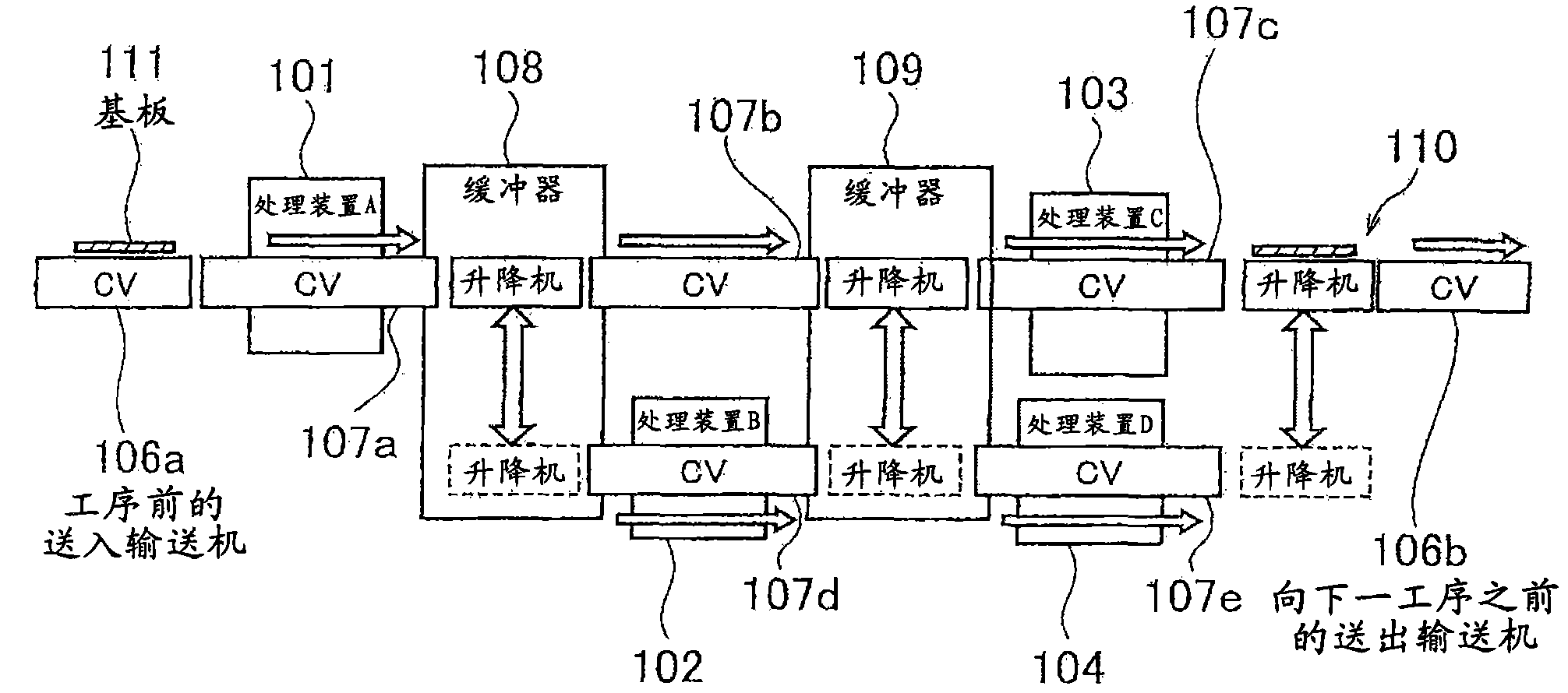
[0074] figure 1 It is a side view showing the structure of the first embodiment of the processing equipment of the present invention
[0075] In the processing device of this embodiment, as figure 1 As shown, there are a plurality of conveyance paths for conveyed objects among the plurality of processing devices 101 , 102 , 103 , and 104 . Also, along this conveyance path, a plurality of conveyors with a branching function (hereinafter referred to as branching conveyors, FCV: conveying unit) 107a, 7, 107b, 107c, 107d for conveying substrates (objects to be conveyed) 111 are provided. . The plurality of substrates 111 are made to correspond to the branch conveyors 107a, 7, 107b, 107c, and 107d.
[0076] In this processing facility, each processing apparatus 101, 102, 103, 104 and each branch conveyor 107a, 7, 107b, 107c, 107d are installed in multiple stages. The first processing device 101 and the third processing device 103 are provided in the upper stage, and the second ...
no. 3 approach
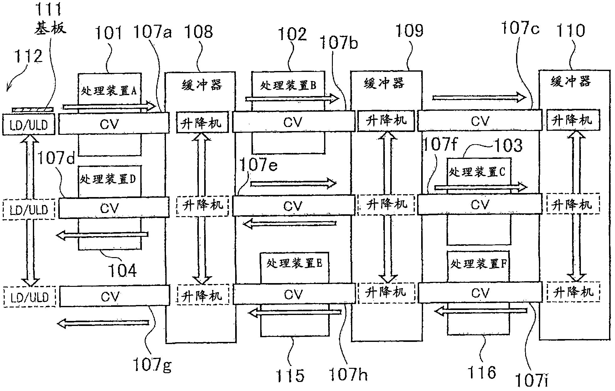
[0096] image 3 It is a side view showing the structure of the third embodiment of the processing facility of the present invention.
[0097] In the processing device of this embodiment, if image 3 As shown, the processing device and the branch conveyor are arranged in three stages. That is, in this processing facility, the first and second processing devices 101 and 102 are provided at the upper stage, the third and fourth processing devices 103 and 104 are provided at the middle stage, and the fifth and sixth processing devices 115 and 116 are provided at the lower stage. In addition, the first to third branch conveyors 107a, 107b, and 107c are installed in the upper stage, the fourth to sixth branch conveyors 107d, 107e, and 107f are installed in the middle stage, and the seventh to ninth branch conveyors 107g and 107h are installed in the lower stage. , 107i.
[0098] In this processing facility, the board|substrate 111 is carried in to the 1st branch conveyor 107a fro...
PUM
Abstract
The present invention provides processing equipment, a conveying control device and a conveying control method. The processing equipment is provided with a plurality of conveying paths between each processing unit. the processing equipment weights a standby time of each object to be conveyed at each time, the load conditions of processing units of a conveying destination and a conveying source, the entire load condition of the conveying zone of each object to be conveyed, and the load condition of each conveying unit separately, the priority of each conveying treatment is calculated by the weighting alteration corresponding with the condition of the conveying zone so as to determine an object to be conveyed to the processing device to control the conveying units. The processing equipment will not be large, will not increase the period of produce and development, and has an enough conveying capacity. According to the processing equipment, when the load of the object to be conveyed to a conveying destination is high, it is capable of shortening the production pitch time of the whole processing unit.
Description
[0001] This application is a divisional application of the patent application submitted on June 22, 2009, with the application number 200910142508.4, and the title of the invention is "processing equipment, transportation control device and transportation control method". technical field [0002] The present invention relates to a processing facility having a transport unit for transporting objects to be transported on these transport paths when there are transport paths for objects to be transported such as a plurality of substrates between a plurality of processing apparatuses, and a method of controlling the transport unit of the processing apparatus A transport control device, a transport control method for controlling a transport unit of the processing facility. Background technique [0003] Conventionally, there is a processing facility in which there are a plurality of conveying paths that branch or merge conveyed objects such as substrates between a plurality of proce...
Claims
Application Information
Patent Timeline
Application Date:The date an application was filed.
Publication Date:The date a patent or application was officially published.
First Publication Date:The earliest publication date of a patent with the same application number.
Issue Date:Publication date of the patent grant document.
PCT Entry Date:The Entry date of PCT National Phase.
Estimated Expiry Date:The statutory expiry date of a patent right according to the Patent Law, and it is the longest term of protection that the patent right can achieve without the termination of the patent right due to other reasons(Term extension factor has been taken into account ).
Invalid Date:Actual expiry date is based on effective date or publication date of legal transaction data of invalid patent.

