Processing equipment, conveying control device and conveying control method

A processing device and processing equipment technology, which is applied to conveyor control devices, program control in sequence/logic controllers, conveyors, etc., can solve the problems of long development cycle and increased product volume, saving space, reducing The effect of the amount of work in process and the reduction of the lead time

Inactive Publication Date: 2009-12-23
IHI CORP
View PDF5 Cites 28 Cited by
  • Summary
  • Abstract
  • Description
  • Claims
  • Application Information

AI Technical Summary

Problems solved by technology

[0020] However, in the conventional processing equipment that transports each storage tank, since the transport is not performed when a certain amount of objects to be transported is not inserted into the storage tank, the amount of work in progress increases and the development cycle becomes longer. The problem

Method used


Image

  • Processing equipment, conveying control device and conveying control method
  • Processing equipment, conveying control device and conveying control method
  • Processing equipment, conveying control device and conveying control method

Examples


no. 1 approach

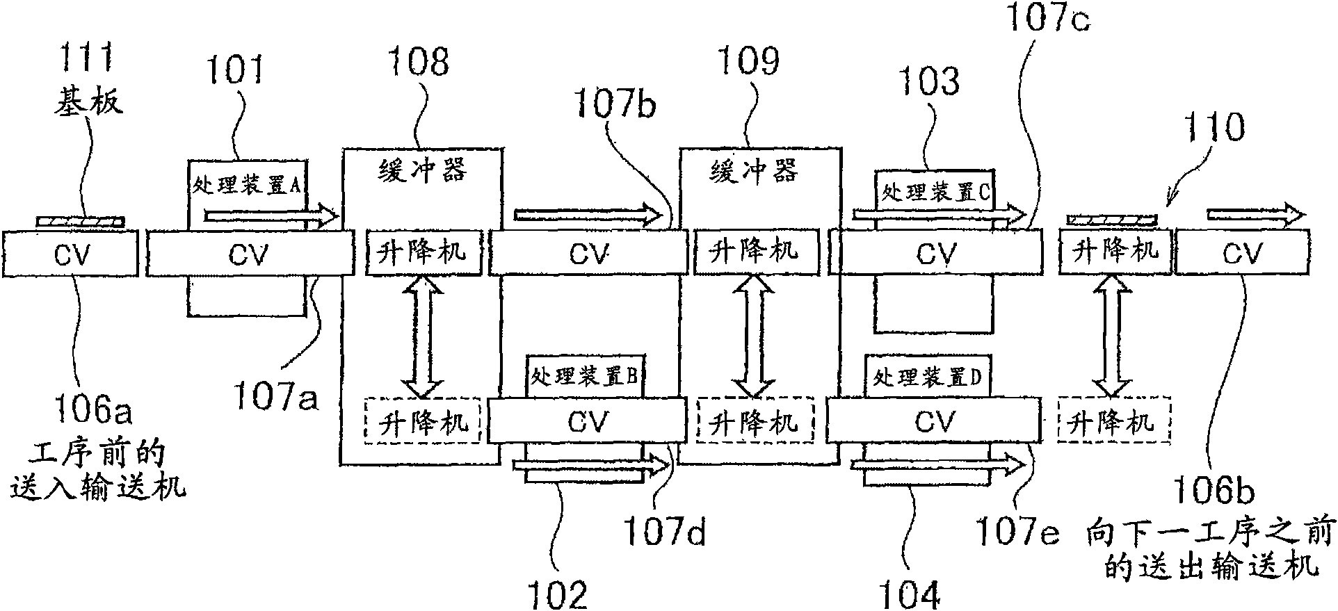
[0073] figure 1 Is a side view showing the structure of the first embodiment of the processing equipment of the present invention

[0074] In the processing equipment of this embodiment, such as figure 1 As shown, there are a plurality of conveying paths for objects to be conveyed between the plurality of processing devices 101, 102, 103, and 104. In addition, along the conveying path, a plurality of conveyors with fork functions (hereinafter referred to as fork conveyors, FCV: conveying units) 107a, 7, 107b, 107c, 107d for conveying substrates (transported objects) 111 are installed. . The plurality of substrates 111 correspond to the fork conveyors 107a, 7, 107b, 107c, and 107d.

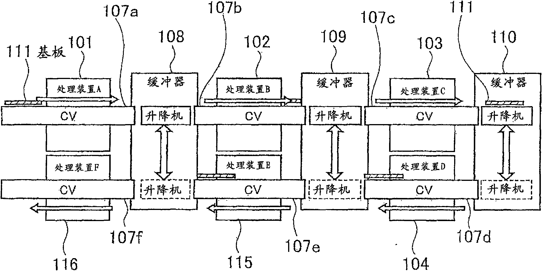
[0075] In this processing facility, each processing device 101, 102, 103, 104 and each branch conveyor 107a, 7, 107b, 107c, 107d are installed in multiple stages. The first processing device 101 and the third processing device 103 are provided at the upper level, and the second processing device 102...

no. 3 approach

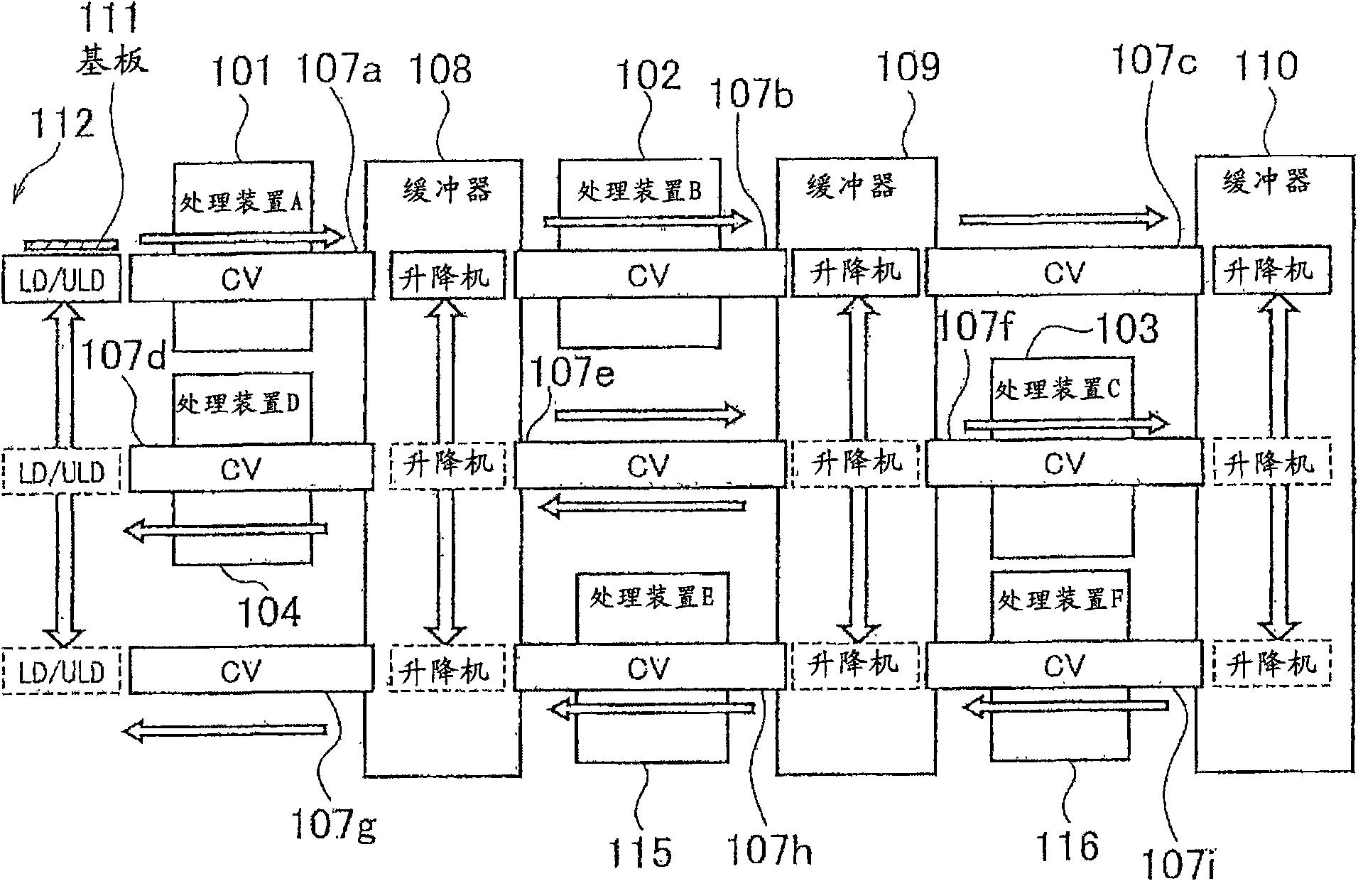
[0095] image 3 It is a side view showing the structure of the third embodiment of the processing equipment of the present invention.

[0096] In the processing equipment of this embodiment, such as image 3 As shown, the processing device and the fork conveyor are arranged in three stages. That is, in this processing facility, the first and second processing devices 101 and 102 are provided at the upper level, the third and fourth processing devices 103 and 104 are provided at the middle level, and the fifth and sixth processing devices 115 and 116 are provided at the lower level. In addition, the first to third fork conveyors 107a, 107b, 107c are installed at the upper level, the fourth to sixth fork conveyors 107d, 107e, and 107f are installed at the middle level, and the seventh to ninth fork conveyors 107g, 107h are installed at the lower level. , 107i.

[0097] In this processing facility, the substrate 111 is sent to the first fork conveyor 107a from outside the process. I...


PUM


Abstract

The present invention provides processing equipment, a conveying control device and a conveying control method. The processing equipment is provided with a plurality of conveying paths between each processing unit. the processing equipment weights a standby time of each object to be conveyed at each time, the load conditions of processing units of a conveying destination and a conveying source, the entire load condition of the conveying zone of each object to be conveyed, and the load condition of each conveying unit separately, the priority of each conveying treatment is calculated by the weighting alteration corresponding with the condition of the conveying zone so as to determine an object to be conveyed to the processing device to control the conveying units. The processing equipment will not be large, will not increase the period of produce and development, and has an enough conveying capacity. According to the processing equipment, when the load of the object to be conveyed to a conveying destination is high, it is capable of shortening the production pitch time of the whole processing unit.

Description

Technical field [0001] The present invention relates to a processing device having a conveying unit for conveying the conveyed objects on these conveying paths when there are conveying paths for conveyed objects such as a plurality of substrates between a plurality of processing apparatuses, and a conveying unit that controls the processing equipment A conveying control device and a conveying control method of a conveying unit that controls the processing equipment. Background technique [0002] At present, there is a processing facility in which there are multiple branching or merging conveying paths with substrates and other conveyed objects between multiple processing devices, and a conveying unit that conveys the conveyed objects on these conveying paths. Each conveyed object corresponds to one conveying unit. [0003] As processing equipment with such branching or merging conveyance paths, it is common to have elevators that go up and down between the floors in the room wher...

Claims


Application Information

Patent Timeline
Patent Type & Authority Applications(China)
IPC IPC(8): B65G37/00B65G49/06B65G49/07B65G47/52B65G43/00B65G43/10G05B19/04H01L21/677
Inventor 志田伦教
Owner IHI CORP
Why Eureka
Try Eureka