
Waste incineration fly ash melting treatment device

A waste incineration fly ash and processing device technology, which is applied in the field of waste incineration fly ash treatment, can solve the problems of inability to fully melt, fail to improve fly ash melting efficiency, and single stirring direction, so as to improve melting efficiency and reduce cleaning work Frequency, the effect of increasing the rate of agitation

Pending Publication Date: 2022-05-10
江西鑫泉固废处理有限公司
View PDF0 Cites 0 Cited by
  • Summary
  • Abstract
  • Description
  • Claims
  • Application Information

AI Technical Summary

Problems solved by technology

[0002] With the development of society, people's quality of life is getting better and better, followed by a large amount of waste incineration fly ash. The incineration fly ash treatment method is to incinerate domestic waste incineration fly ash through a melting treatment device. Generally, the waste incineration fly ash to be treated is put into the device, and then the air in the device is heated to about 1300 ° C, and the agitation component is positioned on the The fly ash in the device is stirred to ensure that the fly ash will be in full contact with the high-temperature air, and will not be fully melted due to accumulation
[0003] Existing agitation components generally perform agitation in one direction, and the agitation direction is too single, so that only part of the fly ash can be agitated, and the overall melting efficiency of the fly ash cannot be improved

Method used


Image

  • Waste incineration fly ash melting treatment device
  • Waste incineration fly ash melting treatment device
  • Waste incineration fly ash melting treatment device

Examples


Embodiment Construction

[0031] The following will clearly and completely describe the technical solutions in the embodiments of the present invention with reference to the accompanying drawings in the embodiments of the present invention. Obviously, the described embodiments are only some, not all, embodiments of the present invention.

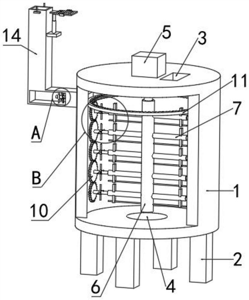
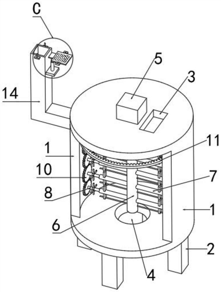
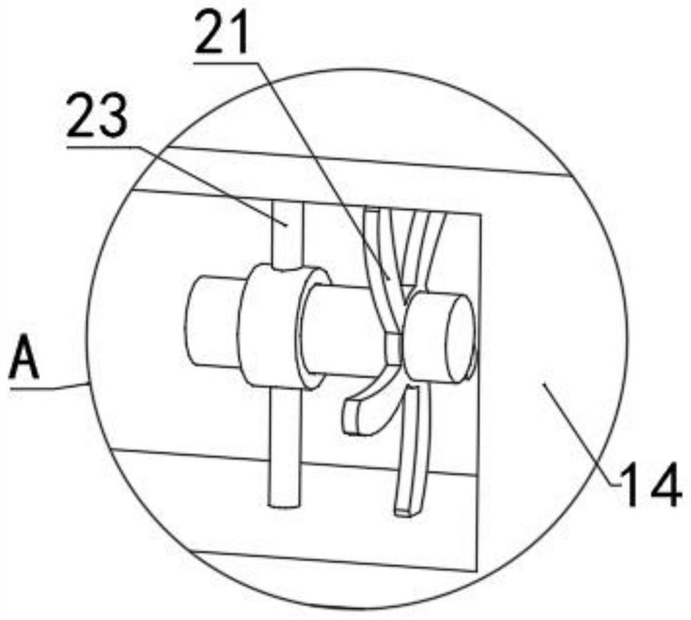
[0032] refer to Figure 1-5 , a waste incineration fly ash melting treatment device, comprising:

[0033] Barrel body 1, a plurality of supporting legs 2 are provided on the lower surface of barrel body 1, a heating device is provided in the side wall of barrel body 1, and a material inlet 3 and a material outlet 4 are respectively provided on the upper surface and lower surface of barrel body 1;

[0034] The smoke outlet component is used to discharge the gas accumulated in the barrel body 1;

[0035] The first stirring assembly, the first stirring assembly is used to stir the garbage fly ash in the barrel body 1 in the horizontal direction, the first stirring asse...


PUM


Abstract

The invention discloses a melting treatment device for waste incineration fly ash. The melting treatment device comprises a barrel body; the first stirring assembly comprises a servo motor fixedly installed on the upper surface of the barrel body, a rotating shaft and a plurality of stirring rods rotationally installed on the side wall of the rotating shaft, and an output shaft of the servo motor penetrates into the barrel body and is fixedly connected with one end of the rotating shaft; the disturbance assembly comprises a plurality of rotating rods and a plurality of disturbance rods; the rotating rods are fixedly mounted at the ends, away from the rotating shaft, of the stirring rods respectively; the disturbance rods are fixedly mounted on the rotating rods respectively; and the driving part is used for providing driving force for the multiple rotating rods to rotate in the vertical direction together. Through cooperation of the first stirring assembly, the disturbance assembly and the driving component, fly ash in the barrel body is not only stirred in the horizontal direction, but also stirred in the vertical direction, the stirring directions are diversified, the flow speed of air in the barrel body can be increased, and the overall melting efficiency of the fly ash is improved.

Description

technical field [0001] The invention relates to the technical field of waste incineration fly ash treatment, in particular to a waste incineration fly ash fusion processing device. Background technique [0002] With the development of society, people's quality of life is getting better and better, followed by a large amount of waste incineration fly ash. Ashes, generally put the waste incineration fly ash to be processed into the device, and then heat the air in the device to about 1300°C, and make the stirring component stir the fly ash in the device to ensure that the fly ash will be mixed with the high temperature air Full contact will not cause insufficient melting due to accumulation. [0003] Existing agitation components generally perform agitation in one direction, and the agitation direction is too single, so that only part of the fly ash can be agitated, and the overall melting efficiency of the fly ash cannot be improved. Contents of the invention [0004] The...

Claims


Application Information

Patent Timeline
IPC IPC(8): F23G5/28F23G5/32F23G5/033F23J3/02F23J15/02
CPCF23G5/28F23G5/32F23G5/033F23J3/02F23J15/025F23G5/245F23G2200/00F23G2209/30
Inventor 金强熊健
Owner 江西鑫泉固废处理有限公司
Learn More