Tension adjusting mechanism for copper foil surface treating machine

A technology of surface treatment machine and tension adjustment, which is applied in the direction of thin material processing, coiling, transportation and packaging, etc., which can solve the problem of not being able to meet constant tension at any time, smooth winding and unstable winding tension, which affect the collection of copper foil. Roll quality and other issues, to achieve the effect of simple installation, flexible movement, and easy use

CN102502309AActive Publication Date: 2012-06-20XIAN AEROSPACEMOTOR MACHINE FACTORY
9 Cites 18 Cited by

Patent Information

Authority / Receiving Office
CN · China
Current Assignee / Owner
Publication Date
2012-06-20

Smart Images

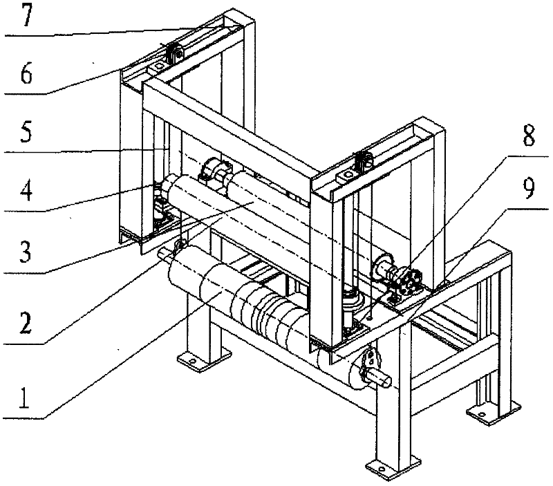
  • Figure 1
    Figure 1
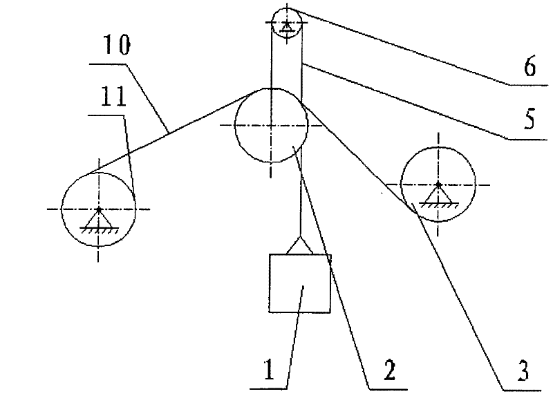
  • Figure 2
    Figure 2
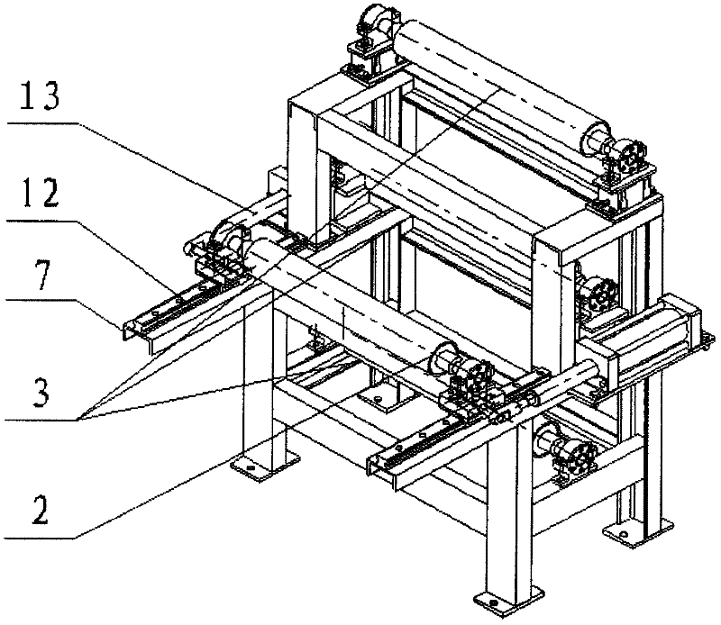
  • Figure 3
    Figure 3
Patent Text Reader

Abstract

The invention relates to a tension adjusting mechanism for a copper foil surface treating machine; an upper bracket is fixed on the upper surface of a lower bracket; a guide roller is arranged in the middle of the upper surface of the lower bracket; a counterweight roller is positioned at one side of a tension adjusting roller and below the longitudinal beam of the lower bracket; the counterweight roller is hung at one end of a steel wire rope by virtue of fixed pulleys; the tension adjusting roller is positioned at the other side of the counterweight roller and above the longitudinal beam of the lower bracket; the tension adjusting roller is arranged on guide rod fixing seats positioned on the upper surface of the lower bracket; the pair of fixed pulleys are respectively arranged on the upper surface of a longitudinal beam of the upper bracket; the pair of guide rod fixing seats are respectively positioned on the upper surface of the lower bracket and the lower surface of the longitudinal beam of the upper bracket; and the positions of the two guide rod fixing seats correspond to each other. The tensile force generated by the gravity of a counterweight block is direct, and a copper foil is ensured to be tensioned since the change of the tensile force generated by the instant relaxation and tension of the copper foil can be made up by the movement of the tension adjusting roller at any time, so that the tensile force of the rolled copper foil is guaranteed to be constant. The tension adjusting mechanism has the characteristics of being simple in processing and installing as well as simple and convenient to operate, control and use.
Need to check novelty before this filing date? Find Prior Art

Description

technical field

[0001] The invention relates to a component of copper foil surface treatment equipment, in particular to a tension adjustment mechanism that adjusts the tension through the instantaneous movement of a tension adjustment roller to ensure that the tension of copper foil winding is constant and flat. Background technique

[0002] Electrolytic copper foil is one of the basic materials in the electronics industry. In addition to being used in bypass busbars, radio wave shielding plates, high-frequency busbars and heat collectors, more than 90% of it is used to manufacture printed circuit boards and transmit electrical signals.

[0003] Electrolytic copper foil is currently the main manufacturing method for copper foil used in the electronics industry. The method is to use the principle of electrochemistry, and under the action of the supporting system, a certain concentration of electrolyte is sent into the foil machine. After obtaining two electrons, copper atom...

Examples

Embodiment Construction

[0047] This embodiment includes a counterweight roller 1, a tension adjustment roller 2, a guide roller 3, a linear bearing pair 4, a steel wire rope 5, a pair of fixed pulleys 6, an upper bracket 7, two pairs of guide rod fixing seats 8 and a lower bracket 9. Both the upper bracket 7 and the lower bracket 9 are frame structures, and the upper bracket 7 is fixed on the upper surface of the lower bracket 9 . The guide roller 3 is installed in the middle of the upper surface of the lower bracket 9; the counterweight roller 1 is located on one side of the tension adjustment roller 2, below the longitudinal beam of the lower bracket 9, and is hung on one end of the steel wire rope 5 through the fixed pulley 6; The other side of heavy roller 1, the top of lower bracket 9 longitudinal beams, is contained on the guide rod holder 8 that is positioned at lower bracket 9 upper surfaces. A pair of fixed pulleys 6 are installed on the fixed pulley fixed plate 27 respectively, and the fixe...