Supercharge Your Innovation With Domain-Expert AI Agents!

Hydraulic brake device

A brake device and water brake technology, which is applied to drilling equipment and methods, mechanical equipment, construction, etc., can solve the problems of laborious operation, fast wear of brake belts, and serious heat generation, and achieve easy operation, low manufacturing and maintenance costs , easy maintenance effect

Active Publication Date: 2013-07-31
JIANGSU WUXI MINERAL EXPLORATION MASCH GENERAL FAB CO LTD
View PDF6 Cites 0 Cited by
  • Summary
  • Abstract
  • Description
  • Claims
  • Application Information

AI Technical Summary

Problems solved by technology

When drilling into a deep hole, the weight of the entire set of drill pipes will exceed 10 tons. The commonly used method is to rely on the descending brake to control the descending speed or brake. Add auxiliary deceleration device

Method used


Image

  • Hydraulic brake device
  • Hydraulic brake device

Examples


Embodiment Construction

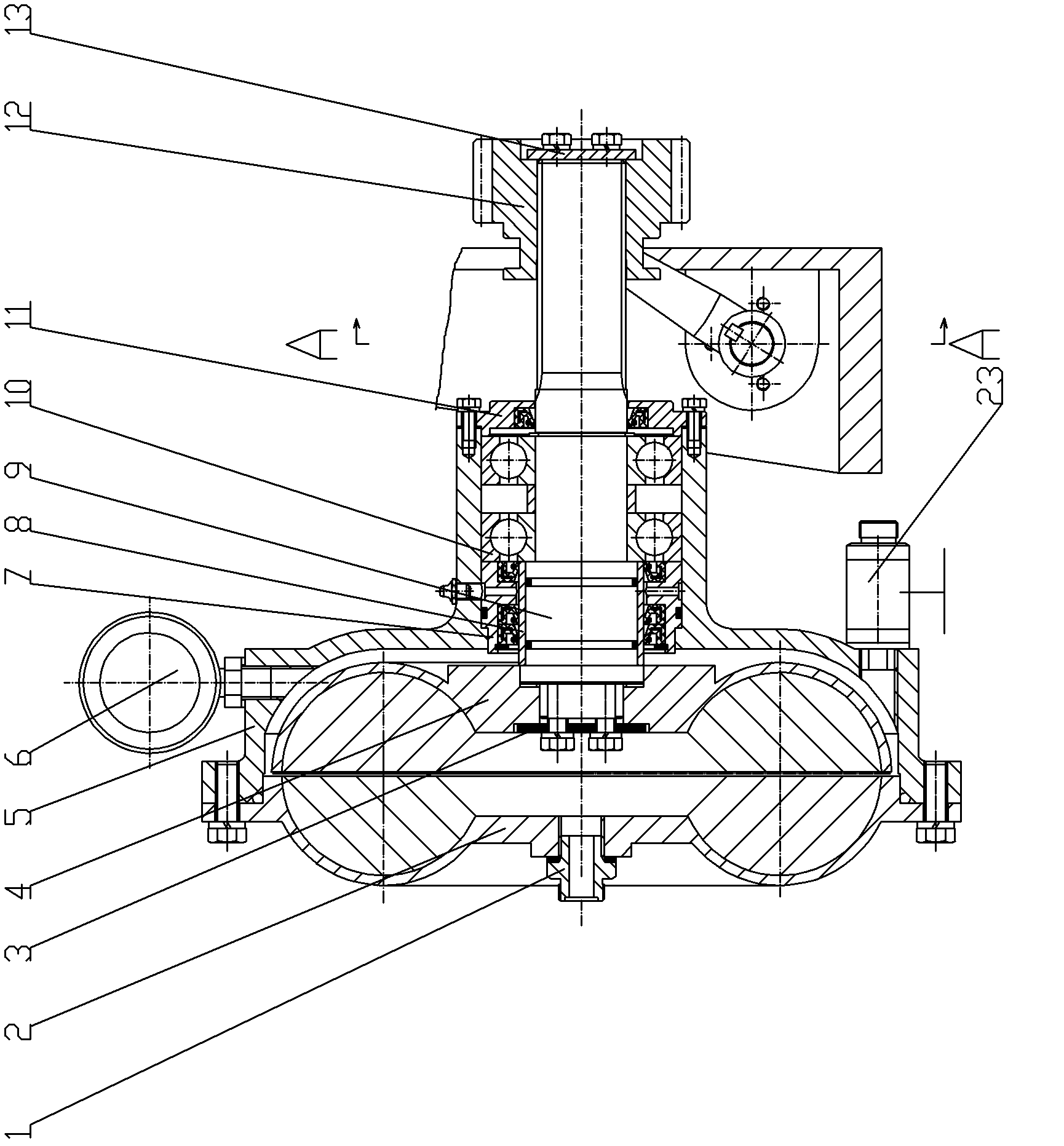
[0012] Below the present invention will be further described in conjunction with the embodiment in the accompanying drawing:

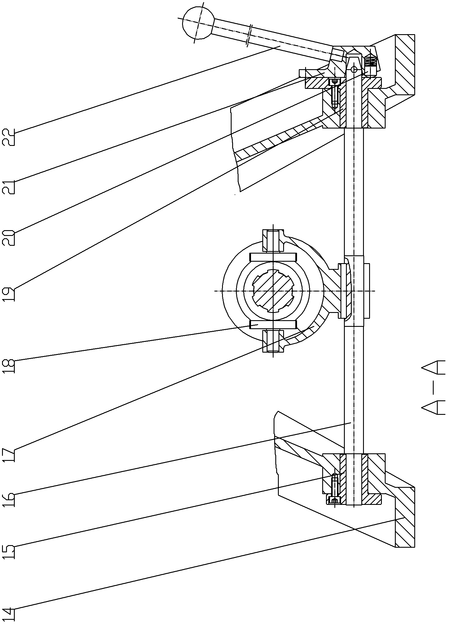
[0013] Including water inlet joint 1, stator 2, first baffle plate 3, rotor 4, housing 5, pressure gauge 6, first bushing 7, second bushing 8, main shaft 9, bearing 10, end cover 11, slip Gear 12, second baffle plate 13, bearing 14, first positioning sleeve 15, shift fork shaft 16, shift fork 17, shift block 18, second positioning sleeve 19, positioning pin 20, handle base 21, handle 22, back water valve 23,

[0014] The water inlet joint 1 is installed on the stator 2, and the stator is fixed, and blades with the same angle are welded on its inner surface, and the stator 2 is fixed on the housing 5 by bolts. Pressure gauge 6 is installed on the upper end of housing 5, can show water pressure. Backwater valve 23 is installed in the lower end of housing 5, and backwater valve 23 is adjustable, can control the water discharge speed by opening and closi...


PUM


Abstract

The invention relates to a hydraulic brake device. The hydraulic brake device comprises a water inlet connector which is mounted on a stator, the stator is fixed on a shell by a bolt; a spindle is mounted on the shell through a bearing, a first shaft sleeve and a second shaft sleeve; an external end is axially located by an end cover and fixed on the shell by a screw; a rotor is fixed on the spindle by the bolt through a first baffle, a slippage gear is mounted on the spindle through a spline structure, a shifting block is driven by a shifting fork to axially slide along the spindle, and a right end face is fixed by the second baffle and the bolt; the shifting fork is fixed on a support through a first locating sleeve and a second locating sleeve; the shifting fork is mounted on the shifting forking shaft through a flat key to perform the synchronous shifting; a handle is fixed on a handle base through the thread, and the handle base is connected with the shifting fork shaft through alocating pin. The hydraulic brake device provided by the invention is safe and reliable, can stably control the descending speed of a drilling tool in labor-saving, is easy to operate, stable and labor-saving, convenient for maintenance, and low in manufacturing and maintenance cost and strong in applicability, and can adapt to adverse work condition of the drilling tool.

Description

technical field [0001] The invention relates to a water brake device. Specifically, a water pump is used to supply water to the water brake housing, so that the rotor generates resistance, hinders the rotation of the rotor, realizes the function of controlling the descending speed of the drilling tool, and finally realizes the control of the descending speed of the drilling tool. It belongs to construction machinery (rig) field. Background technique [0002] In the prior art, the working conditions of the drilling construction are harsh, and the structure of the machine is designed according to the principles of simplicity, practicality, safety and reliability; it is required to be easy to install and disassemble, and easy to maintain, so it is suitable for use in field areas. When drilling into a deep hole, the weight of the entire set of drill pipes will exceed 10 tons. The commonly used method is to rely on the descending brake to control the descending speed or brake. A...

Claims


Application Information

Patent Timeline
Patent Type & Authority Patents(China)
IPC IPC(8): F16D57/02E21B3/02
Inventor 朱利根
Owner JIANGSU WUXI MINERAL EXPLORATION MASCH GENERAL FAB CO LTD
Features
  • R&D
  • Intellectual Property
  • Life Sciences
  • Materials
  • Tech Scout
  • Unparalleled Data Quality
  • Higher Quality Content
  • 60% Fewer Hallucinations
Learn More