Micro-flow regulating valve

A flow control valve and tiny technology, applied in the field of flow valves, can solve the problems of poor adjustment accuracy, low leakage level, impurity blockage, etc., and achieve the effects of accurate and easy flow control, guaranteed processing strength, and improved leakage level.

Active Publication Date: 2012-06-20
CHONGQING CHUANYI CONTROL VALVE
View PDF4 Cites 21 Cited by
  • Summary
  • Abstract
  • Description
  • Claims
  • Application Information

AI Technical Summary

Problems solved by technology

[0003] There are three main problems in the existing micro-flow regulating valves: 1. The adjustment accuracy is poor, which is reflected in the fact that there is no flow rate in the initial stroke and the flow rate does not change during a stroke; 2. The flow area is scattered and easy to be blocked by impurities; 3. The leakage level is low , can only reach level IV leakage, and cannot meet the requirements of low leakage conditions

Method used


Image

  • Micro-flow regulating valve
  • Micro-flow regulating valve
  • Micro-flow regulating valve

Examples


Embodiment Construction

[0015] Preferred embodiments of the present invention will be described in detail below. It should be understood that the preferred embodiments are only for illustrating the present invention, but not for limiting the protection scope of the present invention.

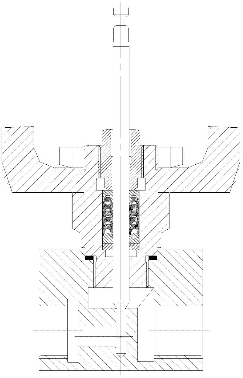
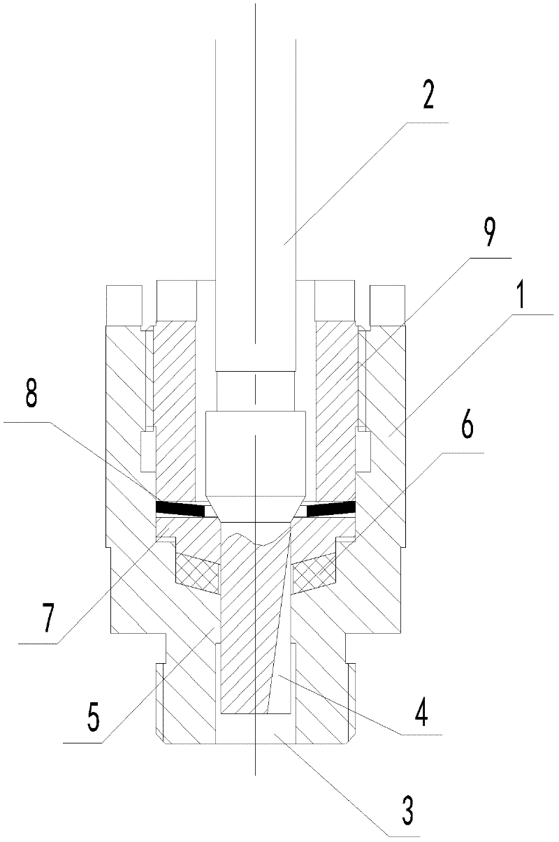
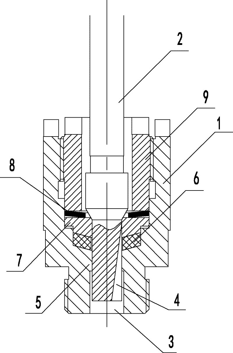
[0016] see figure 2 , a small flow regulating valve, including a sleeve valve seat 1 and a valve core 2 arranged in the sleeve valve seat, a boss 2 is arranged in the water outlet 3 of the sleeve valve seat 1, and the head of the valve core 2 Closely matched with the boss 5, the head side of the valve core 2 is provided with a fluid passage groove 4 that gradually becomes smaller along the water inlet direction. In order to facilitate processing and precise control of the flow rate, the fluid passage groove 4 is triangular. The tank body, the end of the tank body close to the top of the head of the valve core 2 is the bottom edge of the triangle, with the largest flow area, and along the water inlet direction, the fl...


PUM


Abstract

The invention relates to the technical field of flow valves and provides a micro-flow regulating valve, which is high in regulating accuracy and centralized in flow area and comprises a sleeve valve seat and a valve core arranged in the sleeve valve seat. A boss is arranged in a water outlet of the sleeve valve seat, the valve core head is tightly matched with the boss, and a fluid passing through groove with an overflowing area gradually decreased along the water inlet direction is arranged on one side of a valve core head portion. Further, the fluid passing through groove is a triangular groove. The valve core enables the whole flow area to be centralized in the groove from an original annular area and enables a local area to be increased and not to be blocked by small sundries. The overflowing area of the fluid passing through groove is gradually decreased along the water inlet direction so that linear regulating can be achieved. By means of design of the triangular groove, flow regulating can be controlled accurately, processing is easy, the diameter of the valve core can be larger than that of an existing valve core, and processing strength can be ensured.

Description

technical field [0001] The invention relates to the technical field of flow valves, in particular to a flow regulating valve with small flow. Background technique [0002] The micro flow control valve is suitable for the adjustment of small flow. It is characterized by compact structure, small size, light weight, convenient installation and maintenance, and has the characteristics of flow characteristic control in high-precision occasions. figure 1 It is a structural schematic diagram of an existing micro-flow regulating valve. Since it is a micro-flow valve, all its internal parts are relatively small in size, so the valve core and valve stem are designed to form an integral valve core. The bottom hole of the upper valve cover and the Integral spool guide, the valve seat and the valve body are combined as a whole, and the valve body itself is sealed by the valve body, the fluid enters from the upper part and flows out from the lower part, and the spool adjusts the flow rate...

Claims


Application Information

Patent Timeline
Patent Type & Authority Applications(China)
IPC IPC(8): F16K1/00F16K1/38F16K1/42
Inventor 周平王燕蒋永兵
Owner CHONGQING CHUANYI CONTROL VALVE
Why Eureka
Try Eureka