
Valve mounting mechanism, method for controlling position and angle of valve and fire truck

A technology for installing mechanisms and valves, which is applied in the direction of mechanical equipment, pipes/pipe joints/fittings, pipe components, etc. It can solve the problem of difficulty in ensuring the accuracy of valve installation position and angle, difficulty in installation and disassembly, and inability to control the installation position and angle of valves and other problems to achieve the effect of eliminating pipeline manufacturing errors, simple and fast installation and disassembly, and good sealing performance

Inactive Publication Date: 2012-06-20
CHANGSHA ZOOMLION FIRE FIGHTING VEHICLE
View PDF6 Cites 0 Cited by
  • Summary
  • Abstract
  • Description
  • Claims
  • Application Information

AI Technical Summary

Problems solved by technology

[0003] The installation method of the above-mentioned related technology has the following defects: (1) the installation position and angle of the valve cannot be controlled; (2) it is difficult to install and disassemble; (3) when there is a certain manufacturing error in the pipeline, it will also lead to difficulty in ensuring Accuracy of valve installation position and angle

Method used


Image

  • Valve mounting mechanism, method for controlling position and angle of valve and fire truck
  • Valve mounting mechanism, method for controlling position and angle of valve and fire truck
  • Valve mounting mechanism, method for controlling position and angle of valve and fire truck

Examples


Embodiment Construction

[0014] The present invention will be further described below in conjunction with the accompanying drawings and specific embodiments.

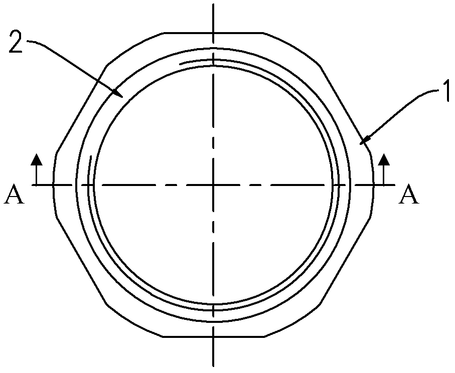
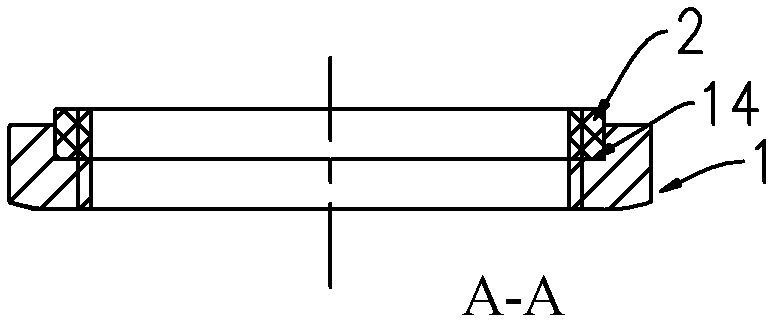
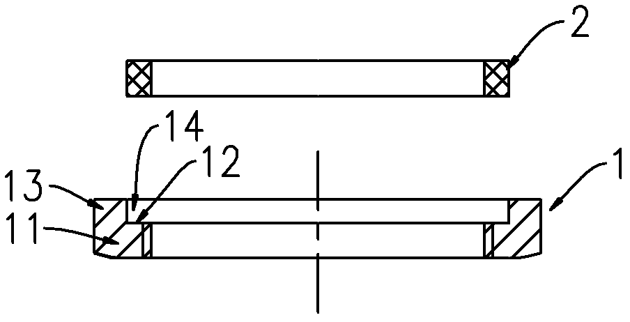
[0015] Figure 1 to Figure 3 A mounting mechanism for a threaded connection type valve in some embodiments of the invention is shown. Such as Figure 1 to Figure 3 As shown, the installation mechanism of the threaded valve includes a locking part 1 and an annular sealing part 2. The locking part 1 includes a nut 11, and the outer half of an end face 12 of the nut 11 extends along the axial direction of the nut 11 to form a The ring body 13 forms an annular stepped portion 14 with the end surface 12 of the nut 11 , and the annular sealing component 2 is disposed on the stepped portion 14 .

[0016] The locking part 1 can be made of metal material in some embodiments. In some embodiments, the sealing member 2 can be made of soft non-metallic materials, such as rubber, silicone and the like.

[0017] The inner diameter of the ring body 13 on t...


PUM


Abstract

The invention provides a valve mounting mechanism, a method for controlling the position and the angle of a valve and a fire truck. The mounting mechanism comprises a locking component and an annular sealing component, the locking component comprises a nut, the outer half portion of an end surface of the nut axially extends along the nut to form a ring, the ring and the end surface of the nut form an annular step, and the annular sealing component is disposed on the step. The fire truck comprises a water supply pipeline and a threaded connecting type valve, and the valve is mounted on the water supply pipeline via the mounting mechanism. The method includes steps of arranging the mounting mechanism onto the pipeline; connecting a connector of the valve with the pipeline in a threaded manner; adjusting the position and the angle of the valve to be proper; screwing the locking component to the direction of the valve; and leading the sealing component to deform so as to be fully filled in a gap among the pipeline, the locking component and the connector of the valve. The mounting mechanism can control the mounting position and the angle of the threaded connecting type valve on the pipeline.

Description

technical field [0001] The present invention relates to an installation mechanism of a valve, in particular to an installation mechanism of a threaded connection valve, to a fire engine using the installation mechanism, and to a method for controlling the installation position and angle of a threaded connection valve with the installation mechanism . Background technique [0002] A large number of threaded ball valves of different sizes are used in the waterway system of fire trucks to control the fluid in the pipeline system. Figure 5 The installation method of the threaded connection type valve in the related art is shown, such as Figure 5 As shown, in the related art, by winding the raw material tape and applying thread sealant on the thread of the pipeline 4 and the pipeline 5, and then connecting the interface part of the valve 3 with them and tightening them, using the raw material tape and the thread Sealants provide a seal between valve threads and pipeline threads...

Claims


Application Information

Patent Timeline
Patent Type & Authority Applications(China)
IPC IPC(8): F16L55/07
Inventor 刘召华胡瑶
Owner CHANGSHA ZOOMLION FIRE FIGHTING VEHICLE
Learn More