Pneumatic high-pressure oil filling device

A pneumatic high-pressure oiler technology, which is applied in the direction of engine components, engine lubrication, delivery pipes/joints, etc., can solve the problems of increased work intensity of operators, insufficient simplicity of the oiler gas circuit, and increased maintenance difficulty, etc., to achieve Convenient inspection and maintenance, reduced maintenance difficulty, convenient and easy connection and disassembly

Active Publication Date: 2014-12-03
ZHEJIANG REFINE WUFU AIR TOOLS
View PDF8 Cites 10 Cited by
  • Summary
  • Abstract
  • Description
  • Claims
  • Application Information

AI Technical Summary

Problems solved by technology

[0002] At present, most of the known butter machines use the reciprocating motion of the pneumatic components to drive the lifting mechanism to increase the oil pressure, and oil the parts that need to be filled with oil through the grease gun. The shell of the lubricator is a one-piece structure, and its disadvantages are as follows: First, when the accessories in the valve train are faulty or need to be overhauled, the pneumatic high-pressure lubricator must be disassembled completely, and the overall disassembly and assembly will be difficult. Cause unnecessary damage and damage to other accessories, increase the work intensity of the operator, lengthen the maintenance time, and increase the maintenance cost; second, the existing oil filling machine is not equipped with a muffler, which makes the exhaust noise louder, and the oil filling of individual structures Although the silencer is provided with the silencer, its installation position is narrow, which is not convenient for disassembly and maintenance; third, the connection position of the air duct on the upper part of the piston is narrow, which is not convenient for disassembly and maintenance; fourth, the internal air circuit of the existing oiler is not simple enough It also increases the difficulty of maintenance

Method used


Image

  • Pneumatic high-pressure oil filling device
  • Pneumatic high-pressure oil filling device
  • Pneumatic high-pressure oil filling device

Examples


Embodiment Construction

[0031] Below in conjunction with accompanying drawing, the present invention will be further described with specific embodiment, see Figure 1-11 :

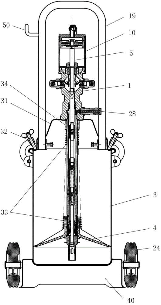
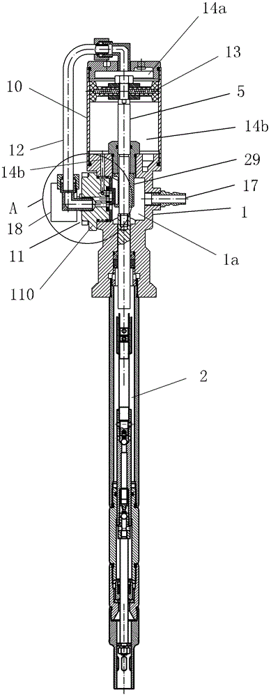
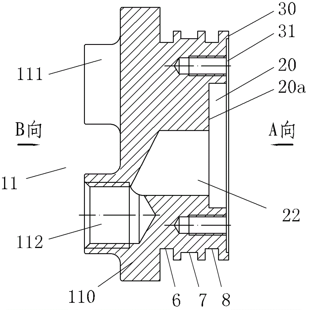
[0032] Pneumatic high-pressure oiler, including a barrel body 3 containing butter, an oil injection pump 1 arranged on the barrel body 3, and an oil injection gun (not shown in the figure) connected to the oil injection pump 1, and the oil injection pump 1 is supplied by a cylinder 10 pressurized by an air source The reciprocating movement drives the oil pressure plate 4 to continuously pressurize the butter entering the grease gun. The reciprocating movement of the piston rod 5 is realized by the automatic control of the reversing valve by the piston rod 5 on the cylinder 10. The reversing valve includes a distribution gas group Cover 11, the middle part of the distribution gas group cover 11 is provided with a mounting part 110, one side is provided with a conduit joint 111 and a muffler installation joint 112 side by side, and...


PUM


Abstract

The invention belongs to the technical field of grease machines and relates to a pneumatic high-pressure oil filling device. An oil filling pump, an oil filling gun connected with the oil filling pump, a push-and-pull armrest and a rolling wheel are arranged on a barrel body. Reciprocating motion of an air cylinder piston rod is achieved by a piston rod control reversing valve. The reversing valve comprises a gas distribution group cover, and an installing portion is arranged in the middle of the gas distribution group cover. A conduit connector, a silencer installing connector and a silencer are arranged on one side of the gas distribution group cover side by side, three annular grooves and three strip-shaped holes are arranged on a cylindrical face on the other side of the gas distribution group cover. The middle strip-shaped hole is communicated with the silencer installing connector, the strip-shaped hole on one side is communicated with the conduit connector and then communicated with an upper cavity of the piston, and the strip-shaped hole on the other side is communicated with a groove on the middle annular groove and then communicated with a lower cavity of the piston. Gas distribution sliding blocks are arranged in the cylindrical grooves and driven by a poking sleeve fixed on the piston rod, and seal rings are arranged on the annular grooves on two sides of the cylindrical face. The pneumatic high-pressure oil filling device has the advantages of being simple in structure, small in noise, convenient to disassemble and decorate and suitable for various oil filling devices.

Description

technical field [0001] The invention belongs to the technical field of butter machines, in particular to a pneumatic high-pressure oiler. Background technique [0002] At present, most of the known butter machines use the reciprocating motion of the pneumatic components to drive the lifting mechanism to increase the oil pressure, and oil the parts that need to be filled with oil through the grease gun. The shell of the lubricator is a one-piece structure, and its disadvantages are as follows: First, when the accessories in the valve train are faulty or need to be overhauled, the pneumatic high-pressure lubricator must be disassembled completely, and the overall disassembly and assembly will be difficult. Cause unnecessary damage and damage to other accessories, increase the work intensity of the operator, lengthen the maintenance time, and increase the maintenance cost; second, the existing oil filling machine is not equipped with a muffler, which makes the exhaust noise lou...

Claims


Application Information

Patent Timeline
Patent Type & Authority Patents(China)
IPC IPC(8): F16N7/38F16N21/00
Inventor 潘灵钢
Owner ZHEJIANG REFINE WUFU AIR TOOLS
Why Eureka
Try Eureka