Direct-water-supply type humidifying system

A technology of humidification system and water inlet pipe, which is applied in the direction of air humidification system, heating and ventilation control system, heating and ventilation safety system, etc. It can solve the problems of large amount of atomization, inconvenient movement, inconvenient centralized management of line control humidifiers, etc. , to achieve the effect of uniform humidification

Inactive Publication Date: 2012-06-20
AUDIOWELL ELECTRONICS GUANGDONG
View PDF4 Cites 11 Cited by
  • Summary
  • Abstract
  • Description
  • Claims
  • Application Information

AI Technical Summary

Problems solved by technology

[0004] (1) Generally, there is only one atomizing humidifier in the factory building. In order to ensure the relative humidity in the large warehouse, the power of these humidifiers is often relatively large, and the amount of atomization is also large, which causes the relative humidity in the factory building to be uneven. ; In addition, since these atomizing humidifiers basically only have one atomizing humidification port, the phenomenon of uneven atomization is further exacerbated. There is basically no humidification effect in the place, and this serious uneven humidification may lead to serious consequences
[0005] (2) Although multiple high-power atomizing humidifiers can be used for larger workshops, these atomizing humidifiers are relatively independent, which is not convenient for unified line control and centralized management of humidifiers, and even if multiple high-power atomizing humidifiers are used Atomized humidifiers, because each atomized humidifier has a relatively wide range of control, it still cannot achieve the purpose of uniform humidification
[0006] (3) Due to the large size and heavy weight of the atomizing humidifier, such an industrial atomizing humidifier occupies a relatively large position and is inconvenient to move, and it is also not easy to install

Method used


Image

  • Direct-water-supply type humidifying system
  • Direct-water-supply type humidifying system
  • Direct-water-supply type humidifying system

Examples


Embodiment Construction

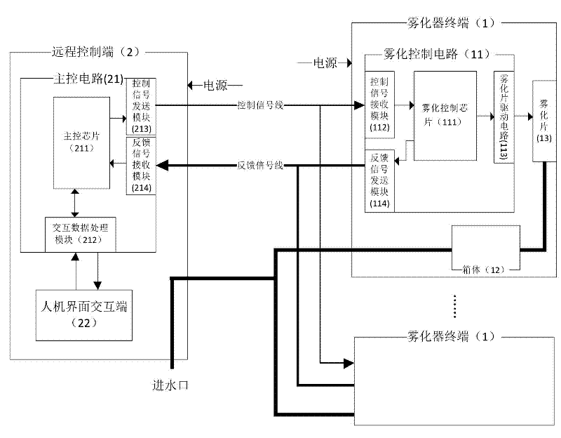
[0029] Reference figure 1 , The system structure diagram of the first embodiment of the present invention includes at least one atomizer terminal 1, and also includes a remote control terminal 2 connected to the atomizer terminal 1 through a control signal line. Each atomizer The device terminal 1 is also connected with a water distribution pipe, and the atomizer terminal 1 realizes different working modes and produces different atomization amounts according to the control signal transmitted from the remote control terminal 2. The atomizer terminals 1 are evenly distributed in the workshop, and the water pipes, power lines, signal lines, etc. are arranged in a centralized and unified manner to make it an effective overall control system. The different working modes are spray atomization at designated time, continuous spray atomization at intervals, preset spray atomization and so on.

[0030] Further as a preferred embodiment, the atomizer terminal 1 is also connected to the remo...


PUM


Abstract

The invention discloses a direct-water-supply type humidifying system which at least comprises an atomizer terminal and also comprises a remote control end, wherein the remote control end is connected to the atomizer terminal by a control signal line; each atomizer terminal is also connected with a water inlet branch pipe, and realizes different working modes and generates different atomizing amount according to control signals transmitted from the remote control end; and the atomizer terminals are uniformly distributed in a workshop. According to the direct-water-supply type humidifying system, since the plurality of atomizer terminals uniformly distributed are adopted, the atomizer terminals are small, are convenient to install and are provided with a plurality of atomizing pieces, and all the atomizer terminals are controlled and managed by the remote control end so as to achieve the purpose of controllable and uniform humidification. As an atomizing and humidifying control system with excellent effect, the direct-water-supply type humidifying system can be widely applied in the industrial production.

Description

Technical field [0001] The invention relates to an industrial control system, in particular to a direct water supply humidification system. Background technique [0002] In modern industrial production and scientific experiments, the importance of air humidity is increasing, and the requirements are getting higher and higher. In many cases, atomizing humidifiers are used. If the humidity cannot meet the requirements, it will cause varying degrees of defects. Consequences, such as precision machining lathes, the humidity requirements of various measuring rooms are generally between 40% and 65% RH, especially in precision bearing finishing, high-precision engraving machines, mechanical measuring rooms, electrical measuring rooms, etc. If the humidity is not enough, the accuracy of the processed products will decrease and the measurement data will be distorted. The humidity requirements of electronic factories, semiconductor factories, program-controlled computer rooms, explosion-pr...

Claims


Application Information

Patent Timeline
Patent Type & Authority Applications(China)
IPC IPC(8): F24F6/12F24F11/02
Inventor 彭波陈伟健熊育虎
Owner AUDIOWELL ELECTRONICS GUANGDONG
Why Eureka
Try Eureka