In-situ test positioning controllable mechanical loading and fixing device

A technology for in-situ testing and fixing devices, applied in measuring devices, instruments, etc., can solve the problems of small loading site and small volume, and achieve the effect of strong repeatability, simple device structure, and accurate positioning test.

Inactive Publication Date: 2012-06-20
BEIHANG UNIV
View PDF2 Cites 8 Cited by
  • Summary
  • Abstract
  • Description
  • Claims
  • Application Information

AI Technical Summary

Problems solved by technology

[0003] In view of the irregular shape of small animal joints (such as the distal femur joint and proximal patella joint of mice used in clinical experiments), the volume is small, the thickness of ar

Method used


Image

  • In-situ test positioning controllable mechanical loading and fixing device
  • In-situ test positioning controllable mechanical loading and fixing device
  • In-situ test positioning controllable mechanical loading and fixing device

Examples


Embodiment Construction

[0050] The present invention will be further described in detail below in conjunction with the accompanying drawings.

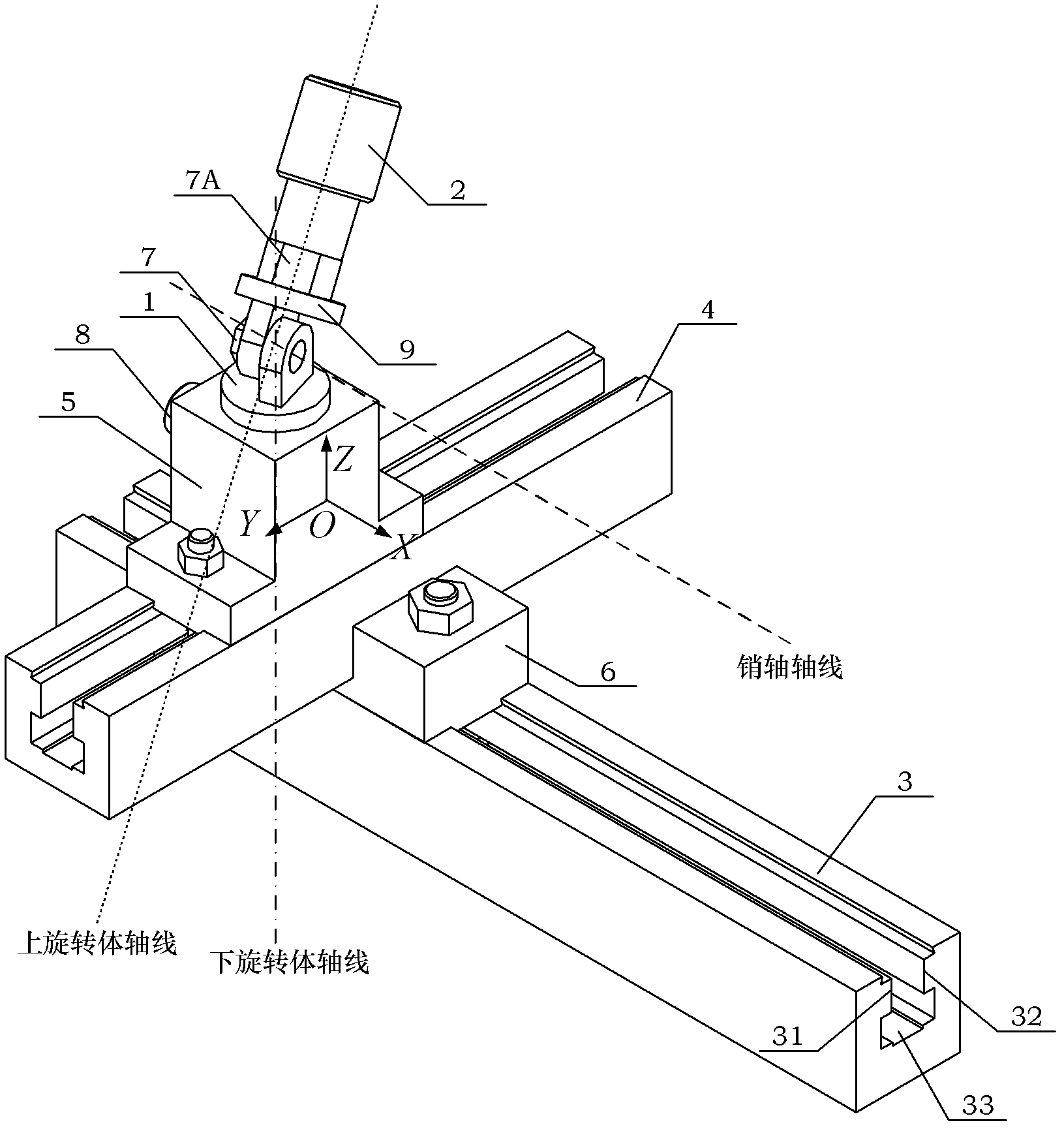
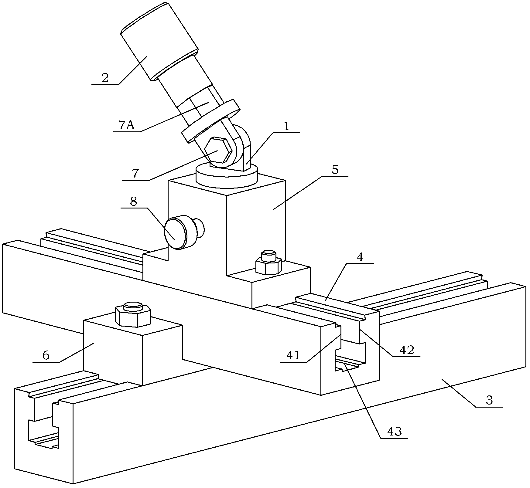
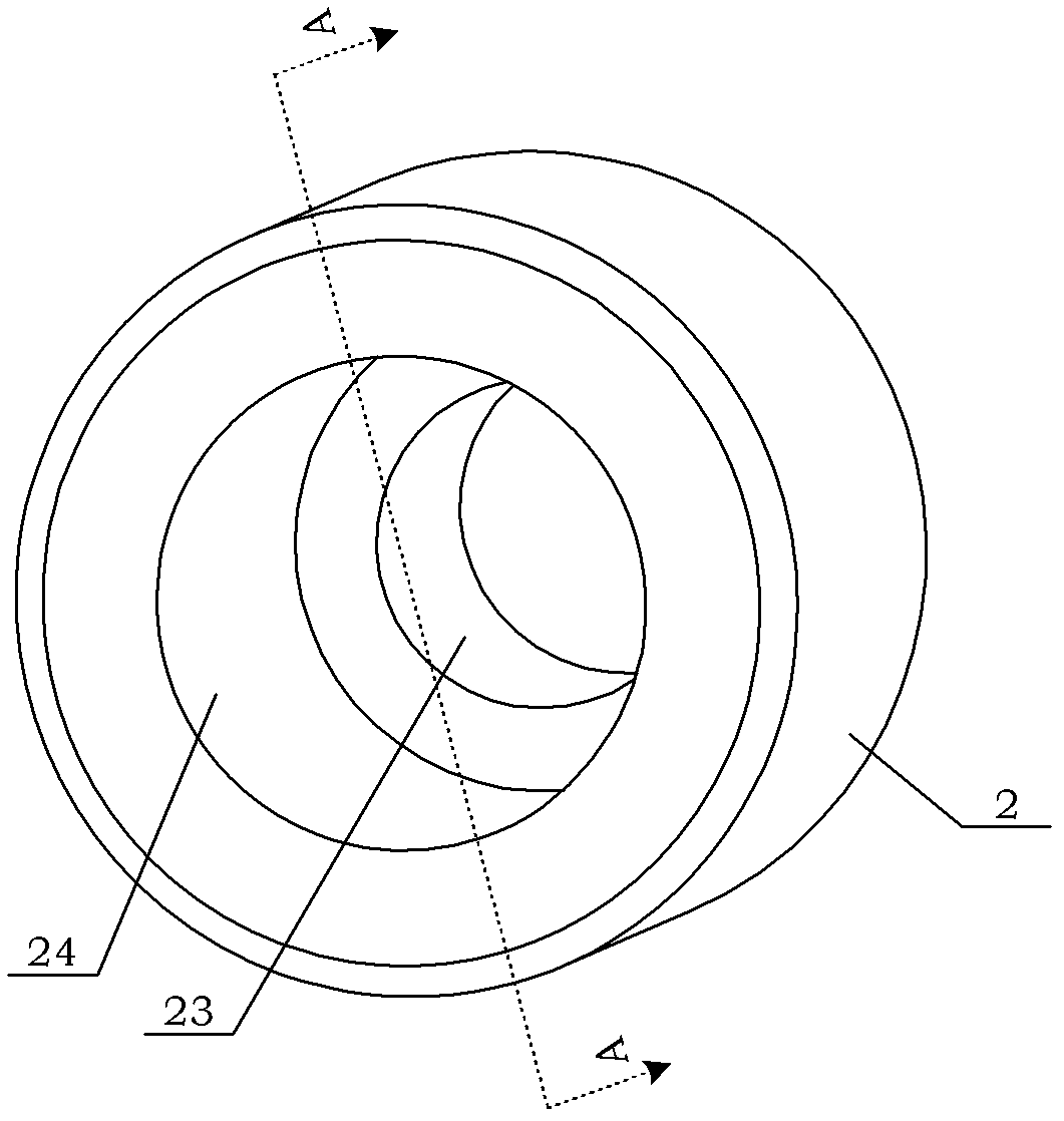
[0051] see figure 1 , Figure 1A , figure 1 As shown in B, the present invention is an in-situ test positioning controllable mechanical loading and fixing device, which includes a lower rotating body 1, an upper rotating body 9, a clamping cylinder 2, an X-axis guide rail 3, and a Y-axis guide rail 4 , sliding base 5, slider assembly 6, self-locking nut 7A, pin shaft 7, locking top nail 8;

[0052] Wherein, the X-axis guide rail 3, the Y-axis guide rail 4 and the slider assembly 6 form a guide rail part;

[0053] Wherein, the upper rotating body 9, the lower rotating body 1, the clamping cylinder 2 and the sliding base 5 form a part of the rotating clamper.

[0054] The mechanical loading fixing device designed by the present invention is a fixture used in conjunction with the existing material mechanics testing machine, and is used in order to solve the ...


PUM


Abstract

The invention discloses an in-situ test positioning controllable mechanical loading and fixing device. A sliding block component (6) of the device is arranged on an X-axis guide rail (3); a sliding block component (6) is arranged on the Y-axis guide rail (4); a sliding base (5) is arranged on the Y-axis guide rail (4); a lower rotating body (1) is arranged on the sliding base (5); the lower rotating body (1) is connected with an upper rotating body (9) by a pin shaft (7); and a clamping cylinder is arranged on the upper rotating body (9). The device disclosed by the invention can quickly and accurately position an irregular experiment sample and can quickly and accurately position the loading site of the experiment sample in situ, thereby greatly reducing the inaccurate positioning problems aroused by the drawbacks of a loading device in an experiment process and improving the accuracy and repeatability of the in-situ test positioning by a mechanical press-in method.

Description

technical field [0001] The present invention relates to a controllable mechanical loading fixing device mainly used for in-situ testing and positioning by press-in method. Background technique [0002] Mechanical indentation measurement is a common method for measuring the thickness of articular cartilage using a mechanical testing machine for materials. As we all know, due to the different material mechanical properties of cartilage tissue and bone tissue, the slopes of the mechanical load-deformation curves of the micro-indenter are different when passing through the cartilage tissue and bone tissue respectively. When the indenter passes through the cartilage layer and touches the bone surface , the pressure will suddenly increase, and the slope of the mechanical load-deformation curve will change significantly, so that the boundary point between cartilage and bone can be determined, and then the cartilage thickness data can be obtained by analysis. [0003] In view of th...

Claims


Application Information

Patent Timeline
IPC IPC(8): G01B21/08
Inventor 王江雪樊瑜波赵峰刘笑宇高玉
Owner BEIHANG UNIV
Why Eureka
Try Eureka