Method for determining vibration working stress limit of aircraft anti-skidding braking control box

A work stress, anti-skid braking technology, applied in vibration testing, testing of machine/structural components, measuring devices, etc., can solve problems such as unrealistic data

Inactive Publication Date: 2012-06-20
XIAN AVIATION BRAKE TECH
View PDF4 Cites 11 Cited by
  • Summary
  • Abstract
  • Description
  • Claims
  • Application Information

AI Technical Summary

Problems solved by technology

The vibration working stress limit test of other foreign electronic products is carried out under non-working conditions. The method of only applying environmental stress without applying working stress is inconsistent with the use state, because the product is subjected to environmental stress and working stress at the same time during use. Yes, the data obtained by using this traditional method experiment is not true

Method used


Image

  • Method for determining vibration working stress limit of aircraft anti-skidding braking control box

Examples


Embodiment 1

[0027] This embodiment is a test to determine the vibration working stress limit for the first type of control box, and the test sample is a set of control boxes. The test sample completed the design improvement for the vibration problem in the development test.

[0028] The test of this embodiment adopts a reliability enhancement test box of model UHS1200, a digital three-purpose meter, a signal source and an oscilloscope.

[0029] The specific process of this embodiment is:

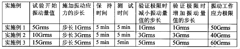
[0030] Step 1. Determine the test parameters. The test parameters include the step starting point of the vibration test, the vibration step length, the vibration duration and performance test time at each step, the step length when verifying the vibration working stress limit, and the finally obtained vibration working stress limit. The starting point of the vibration test step in this embodiment is 5 Grms, the vibration step length is 1 Grms, and the smaller the step length is, the more accurate. The vibrat...

Embodiment 2

[0036] This embodiment is a test to determine the vibration working stress limit for the second type of control box, and the test sample is a set of control boxes. The test sample completed the design improvement for the vibration problem in the development test.

[0037] The test of this embodiment adopts a reliability enhancement test box of model UHS1200, a digital three-purpose meter, a signal source and an oscilloscope.

[0038] The specific process of this embodiment is:

[0039] Step 1. Determine the test parameters. The test parameters include the step starting point of the vibration test, the vibration step length, the vibration duration and performance test time at each step, the step length when verifying the vibration working stress limit, and the finally obtained vibration working stress limit. The vibration test step starting point of this embodiment is 10 Grms, the vibration step length is 3 Grms, and the smaller the step length, the more accurate, the vibration dura...

Embodiment 3

[0045] This embodiment is a test to determine the vibration working stress limit for the third type of control box, and the test sample is a set of control boxes. The test sample completed the design improvement for the vibration problem in the development test.

[0046] The test of this embodiment adopts a reliability enhancement test box of model UHS1200, a digital three-purpose meter, a signal source and an oscilloscope.

[0047] The specific process of this embodiment is:

[0048] Step 1. Determine the test parameters. The test parameters include the step starting point of the vibration test, the vibration step length, the vibration duration and performance test time at each step, the step length when verifying the vibration working stress limit, and the finally obtained vibration working stress limit. The vibration test step starting point of this embodiment is 15 Grms, the vibration step length is 5 Grms, and the smaller the step length is, the more accurate, the vibration du...


PUM


Abstract

The invention discloses a method for determining the vibration working stress limit of an aircraft anti-skidding braking control box. the method comprises the following steps: applying vibrating stress on a control box in a stepping manner to determine the vibration working stress limit of the control box, wherein the step size of the vibration stress applied in a stepping manner is 1-5Grms; the state is kept for 5min every time stepping vibration reaches a specified value to reserve time for vibration stress balancing of the control box, and then a test is performed and lasts for 5min, and the total amount of vibration maintaining time in each step is 10min; and obtaining the vibration working stress limit of a sample piece by using the stepping vibration testing method. According to theinvention, a method that working stress is applied to the control box in the testing process is adopted, and a fault vibration value is determined in time by tracking and observing. If the vibration amount value does not satisfy a design requirement, an improvement advice focused on the vibration performance is proposed. If the vibration amount value satisfies the design requirement, the vibration amount value is taken as an initial value of the vibration working stress limit.

Description

Technical field [0001] The invention relates to the field of electronic products of the landing gear control system of a transportation aircraft, in particular to a method for testing the performance of an aircraft anti-skid brake control box. Background technique [0002] The control box is the control unit in the aircraft's electric anti-skid brake system. It is designed with take-off line brake function, anti-skid function during landing brake, ground protection function during landing, and inter-wheel protection of left and right landing gear wheels during landing, etc. A variety of functions, any function that does not meet the design requirements is a failure. In the present invention, the working performance of the control box refers to the quantitative requirements of the above-mentioned multiple functions. [0003] In order to ensure the reliability and safety requirements of the control box, the high accelerated life test technology is used internationally to stimulate t...

Claims


Application Information

Patent Timeline
Patent Type & Authority Applications(China)
IPC IPC(8): G01M7/02
Inventor 乔建军田广来黄智商海东张谦刘忠平
Owner XIAN AVIATION BRAKE TECH
Why Eureka
Try Eureka