
Reliability test method for photovoltaic component

A technology of photovoltaic modules and test methods, which is applied in the monitoring of photovoltaic systems, single semiconductor device testing, photovoltaic modules, etc., can solve the problems of long cycle, only half the temperature rise and fall, and long test time, so as to speed up the test time and speed up the test. Promote and use, facilitate research and development, and test and evaluate the effect of use

Inactive Publication Date: 2012-06-20
TRINA SOLAR CO LTD
View PDF5 Cites 8 Cited by
  • Summary
  • Abstract
  • Description
  • Claims
  • Application Information

AI Technical Summary

Problems solved by technology

But when fully loaded, the heating and cooling speed is basically only half
[0004] In this test, one cycle takes 6 hours, and 200 cycles takes 1200 hours, which is 50 days, so for the test of photovoltaic modules and materials, the cycle is longer
According to relevant authoritative organizations and papers, 200 cycles are not enough, and 500 cycles are needed to find quality problems, so the test time will be longer

Method used


Image

  • Reliability test method for photovoltaic component
  • Reliability test method for photovoltaic component
  • Reliability test method for photovoltaic component

Examples


Embodiment 1

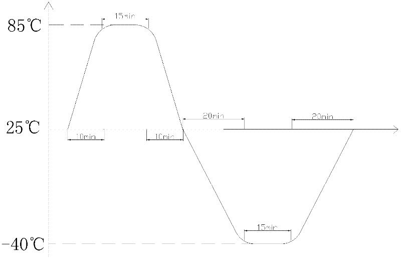
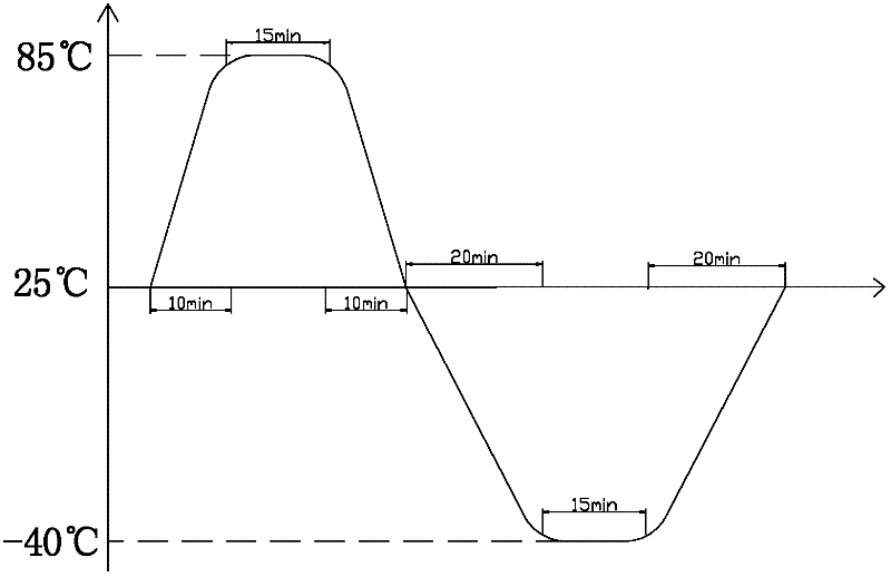
[0018] Such as figure 1 As shown, the specific process is as follows: 1. Raise the temperature of the photovoltaic module from +25°C to +85°C, and it takes 10 minutes; 2. Keep the temperature of the photovoltaic module at 85°C, and keep it warm for 15 minutes; It takes 30 minutes to drop from +85°C to -40°C; 4. When the temperature of the photovoltaic module is kept at -40°C, keep the temperature at low temperature for 15 minutes; 5. It takes time to raise the temperature of the photovoltaic module from -40°C to +25°C 20min; 6. Repeat the process from 1 to 5 100 times.

[0019] exist figure 1 On the basis of , it takes a total of 90 minutes to realize a thermal cycle, 100 cycles are equivalent to 200 conventional thermal cycles, and 200 cycles are equivalent to 500 conventional thermal cycles.

Embodiment 2

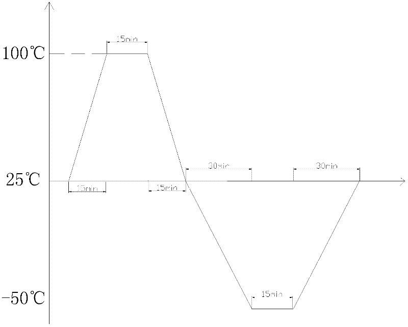
[0021] Such as figure 2 As shown, the process is as follows: 1. Raise the temperature of the photovoltaic module from +25°C to +100°C, which takes 15 minutes; 2. Keep the temperature of the photovoltaic module at 100°C, and keep it warm for 15 minutes; 3. Increase the temperature of the photovoltaic module from It takes 45 minutes to drop from +100°C to -50°C; 4. Keep the temperature of the photovoltaic module at -50°C, and keep it at low temperature for 15 minutes; 5. It takes 20 minutes to increase the temperature of the photovoltaic module from -50°C to +25°C. 6. Repeat the process from 1 to 5 60 times.

[0022] exist figure 2 On the basis of , it takes a total of 120 minutes to realize a thermal cycle, and 60 cycles are equivalent to 500 conventional thermal cycles.

[0023] Taking the tin-coated copper strip of photovoltaic modules as an example, by making small components connected in series with 4pcs cells and a separate tin-coated copper strip, tests and comparison...


PUM


Abstract

The invention relates to the technical field of solar photovoltaic component reliability tests, in particular to a simulated thermal cycle accelerated test method for a photovoltaic component, and aims to improve the performance of a high-temperature thermal cycle test box and a low-temperature thermal cycle test box. By a quick heating method and a quick cooling method, the test time of one thermal cycle of the photovoltaic component is shortened, the test times is reduced, and the total test time consumption is reduced. According to the simulated thermal cycle accelerated test method for the photovoltaic component, the conventional thermal cycle is replaced by the accelerated test method for simulating the thermal cycle, and the material of the photovoltaic component is quickly and effectively tested and evaluated by the method, so that the test time of the thermal cycle of the photovoltaic component is shortened, the method contributes to the research and development and the test and evaluation of photovoltaic materials, and the popularization and the using of the materials in the photovoltaic industry are quickened.

Description

technical field [0001] The invention relates to the technical field of reliability testing of solar photovoltaic components, in particular to a simulated thermal cycle acceleration testing method of photovoltaic components. Background technique [0002] In the reliability test of photovoltaic modules, such as the standard of IEC61215 Crystalline siliconterrestrial photovoltaic (PV) modules-Design qualification and type approval, the test item 10.11 is Thermal cycling testing, and the test requirement is: cycle from -40°C to +85°C for 200 times, and when the temperature of the component is higher than 25°C, pass a forward current to the component, and the current value is the maximum power point current under standard test conditions. The test conditions are as follows Figure 1 . The purpose of the experiments is to evaluate the ability of components and materials to withstand thermal mismatch, fatigue and other stresses due to repeated changes in temperature. [0003] Due...

Claims


Application Information

Patent Timeline
Patent Type & Authority Applications(China)
IPC IPC(8): G01R31/26G01N3/00H02S50/10
CPCY02E10/50
Inventor 徐建美全鹏戴荷琴王昭云
Owner TRINA SOLAR CO LTD
Learn More