Indoor noise source locating method based on beam forming and transfer path analysis

A technology of transmission path analysis and indoor noise, applied in positioning, radio wave measurement systems, measurement devices, etc., can solve problems such as heavy workload, and achieve the effect of reducing workload, accurately locating sound sources, and accurately locating

Inactive Publication Date: 2012-06-20
SHANGHAI JIAO TONG UNIV
View PDF3 Cites 25 Cited by
  • Summary
  • Abstract
  • Description
  • Claims
  • Application Information

AI Technical Summary

Problems solved by technology

However, this method requires separate experiments for each sound source to find its contribution, and the workload increases with the increase of the number of sound sources

Method used


Image

  • Indoor noise source locating method based on beam forming and transfer path analysis
  • Indoor noise source locating method based on beam forming and transfer path analysis
  • Indoor noise source locating method based on beam forming and transfer path analysis

Examples


Embodiment

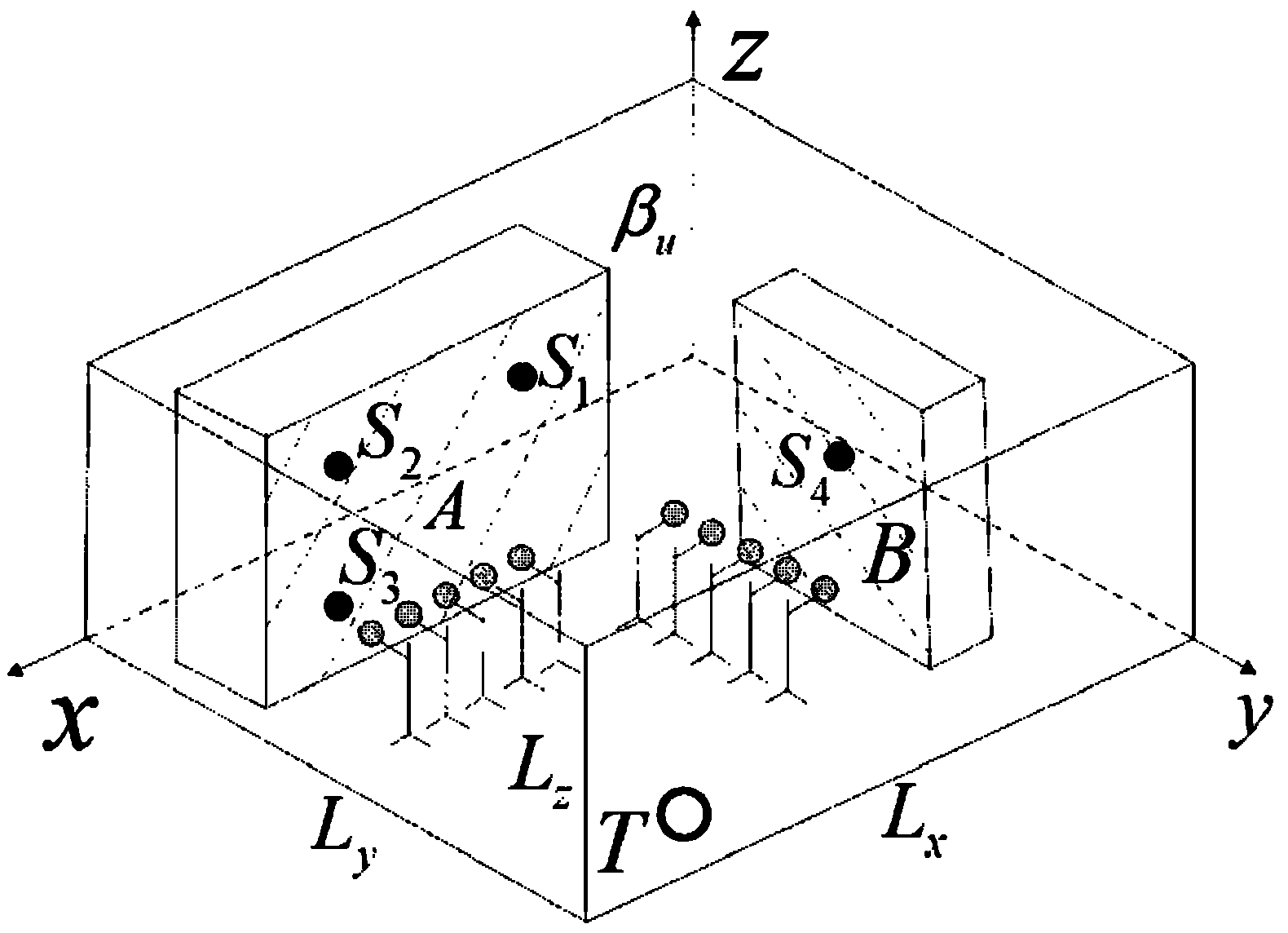
[0044] Indoor sound source identification model such as figure 1 As shown, in a length, width and height are L x , L y , L z In the room, the reflection coefficient of each wall is β u , u=1, 2,..., 6, (β u = 0 means the wall absorbs all incident sound waves; β u = 1 means that the wall totally reflects the incident sound wave), there are point sound sources S in several areas of the room (A, B...) m , m=1, 2, . . . , M.

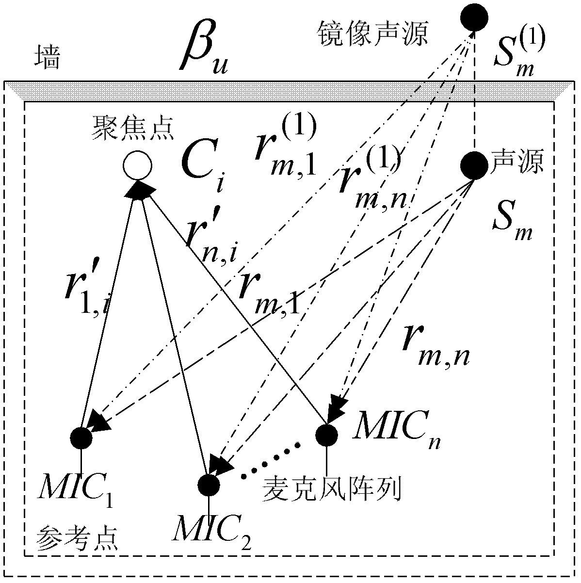
[0045] Beamforming is shown as figure 2 As shown, let the reflection coefficient β of all the walls of the room be u = β, sound source S m After l reflections from each wall, an l-order image sound source S is formed m (l) , then the sound pressure signal received by the nth microphone is the direct sound source S m The sound pressure signal p m,n (t) and the corresponding image source S m (l) sound pressure signal Sum:

[0046] p n ( t ) = ...


PUM


Abstract

The invention relates to an indoor noise source locating method based on beam forming and transfer path analysis. The indoor noise source locating method comprises the steps of: 1), collecting an acoustic pressure signal at a target position under a normal working condition; 2), finding out a maximal acoustic pressure level frequency band by spectrum analysis; 3), dividing regions of possible acoustic sources in a space; 4), finding out the maximal noise source position in each acoustic source region in the space by using a time domain BF (beam forming) method; 5), judging whether all regions are identified completely or not, if so, executing a step 6), and if not, returning to the step 4), 6), measuring path information and contribution degree from each maximal noise source to the target position by using a TPA (transfer path analysis) method, and the like. Compared with prior art, the indoor noise source locating method, disclosed by the invention, has the advantages that: the acoustic source can be accurately located; the work load of the TPA can be reduced, the noise source with the maximal control position can be found out by less TPA work load and the like.

Description

technical field [0001] The invention relates to an indoor noise source positioning method, in particular to an indoor noise source positioning method based on beam forming and transmission path analysis. Background technique [0002] Indoor noise endangers the health of workers. The premise of effective noise control is to determine the main noise source. The work usually includes sound source location and evaluation of the noise contribution of the sound source to the target control position. [0003] Generally, there are some areas where noise sources are relatively concentrated in the indoor environment. The positions and sound spectra of these noise sources are stable, and reverberation is generated indoors. In an anechoic room or an open environment, the sound source localization can adopt a beamforming method (Beamforming, BF) based on a microphone array. However, when this method is applied to sound source localization in a general room, it is easily affected by reve...

Claims


Application Information

Patent Timeline
Patent Type & Authority Applications(China)
IPC IPC(8): G01S5/28
Inventor 成建冯盟黄震宇
Owner SHANGHAI JIAO TONG UNIV
Why Eureka
Try Eureka