
Digital correction method for current/frequency conversion circuit

A frequency conversion circuit and digital correction technology, applied in the direction of adjusting electrical variables, control/regulating systems, instruments, etc., can solve the problems of excessive circuit board size, low correction accuracy, and complicated debugging, and achieve simple implementation and correction steps. Concise, computationally simple effects

Active Publication Date: 2012-06-20
航天科工惯性技术有限公司
View PDF4 Cites 10 Cited by
  • Summary
  • Abstract
  • Description
  • Claims
  • Application Information

AI Technical Summary

Problems solved by technology

The invention corrects the current / frequency conversion circuit, and solves the problems of complex debugging, excessive circuit board size, and low correction accuracy existing in the current / frequency conversion circuit hardware simulation correction

Method used


Image

  • Digital correction method for current/frequency conversion circuit
  • Digital correction method for current/frequency conversion circuit
  • Digital correction method for current/frequency conversion circuit

Examples


Embodiment Construction

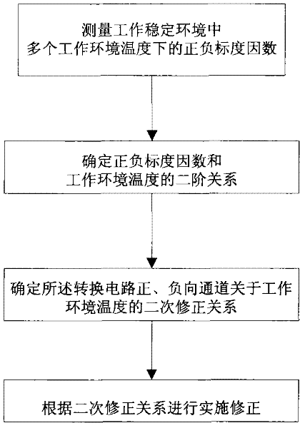
[0029] Below is the combination figure 1 The flow chart shown further introduces this specific implementation manner.

[0030] The output in the current / frequency conversion circuit is a pulse of TTL level, the low level is active, and the pulse width is about 4μs. Pulses are counted with a sampling period of 5ms. Assuming that the input current of the current / frequency conversion circuit is 1mA, the count value of 200 sampling periods is accumulated, and the accumulated result is the pulse number of 1s, that is, the positive scaling factor K + ; If the input current is -1mA, then it is a negative scale factor K - .

[0031] Put the conversion circuit into the temperature test chamber, and use the actual working temperature environment (-40°C to 60°C) of the conversion circuit described in this embodiment to make the conversion circuit at -40°C, -30°C, -20°C, - Work at 11 set ambient temperatures of 10°C, 0°C, 10°C, 20°C, 30°C, 40°C, 50°C, and 60°C, respectively measure th...


PUM


Abstract

The invention discloses a digital correction method for a current / frequency conversion circuit. The digital correction method includes a first step of measuring and acquiring positive and negative scale factors and the temperature of a working environment of the current / frequency conversion circuit; a second step of determining second-order relationship of the positive and negative scale factors and the temperature of the working environment; a third step of determining secondary correction relationship of a forward channel and a reverse channel of the conversion circuit relative to the temperature of the working environment according to the second-order relationship of the positive and negative scale factors and the temperature of the working environment; and a fourth step of correcting output of the conversion circuit by the aid of the correction relationship. The digital correction method for the current / frequency conversion circuit solves problems that a hardware analog correction method for a current / frequency conversion circuit is complicated in debugging, a circuit board is overlarge in size, and correction precision is low.

Description

technical field [0001] The invention relates to a digital correction method for a current / frequency conversion circuit, which can be used to improve the temperature drift characteristics and asymmetry of the scale factor of the current / frequency conversion circuit. Background technique [0002] The current / frequency conversion circuit completes the conversion from the current to the pulse frequency, and the output pulse frequency is proportional to the input current, so as to realize the digitization of the analog information of the current. The output pulse frequency corresponding to each milliamp of input current is called the scaling factor of the current / frequency conversion circuit. Because the parameters of the components of the conversion circuit have certain temperature drift characteristics, and the positive and negative channels are independent and asymmetrical, it is necessary to correct the temperature drift and asymmetry of the scaling factor of the current / freq...

Claims


Application Information

Patent Timeline
Patent Type & Authority Applications(China)
IPC IPC(8): G05F1/565
Inventor 陈鹏赵洪利庞葳刘建华梁杰余莉张秋月陈京谊孙瑶瑶
Owner 航天科工惯性技术有限公司
Learn More