
Annular array thermoelectric generator with functional gradient thermoelectric arms

A technology of thermoelectric generators and functional gradients, applied in the direction of generators/motors, electrical components, etc., can solve the problems of lack of research on the comprehensive design and application of thermoelectric generators, and the lack of research reports on thermoelectric generators, so as to improve the output power and work efficiency, easy installation, and improved utilization

Inactive Publication Date: 2012-06-20
ZHEJIANG UNIV
View PDF5 Cites 6 Cited by
  • Summary
  • Abstract
  • Description
  • Claims
  • Application Information

AI Technical Summary

Problems solved by technology

Domestic research on thermoelectric power generation mainly focuses on the theory of generators and the preparation of thermoelectric materials, but research on the comprehensive design and application of thermoelectric generators is still lacking, so high-performance thermoelectric generators for different occasions are designed has very real meaning
At present, there are few research reports on annular array thermoelectric generators with functional gradients

Method used


Image

  • Annular array thermoelectric generator with functional gradient thermoelectric arms
  • Annular array thermoelectric generator with functional gradient thermoelectric arms
  • Annular array thermoelectric generator with functional gradient thermoelectric arms

Examples


Embodiment Construction

[0027] The present invention will be further described below in conjunction with drawings and embodiments.

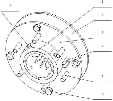
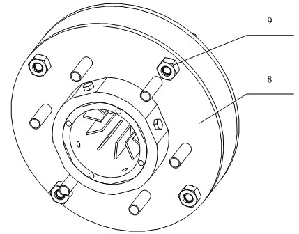
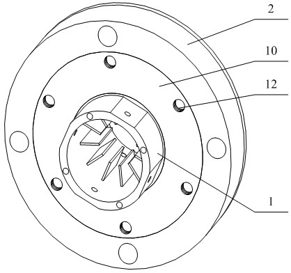
[0028] Such as Figure 1 to Figure 12 As shown, the present invention includes a high-temperature end heat exchanger 1, a low-temperature end heat exchanger 2, a first sleeve 8, a second sleeve 3, a plurality of P-type thermoelectric arms 13, and the same number of P-type thermoelectric arms 13 N-type thermoelectric arm 14, the first sealing ring 12, the second sealing ring 10, the third sealing ring 12 and the fourth sealing ring 10; as Figure 7 , the middle part of the cylinder of the high-temperature end heat exchanger 1 is provided with a plurality of fins 22 symmetrically and equally distributed with both ends, and the cylinder opposite to the fins 22 is provided with a plurality of equally distributed heat transfer arms 19, The outer ends of the cylinder without fins 22 are respectively provided with equally distributed threaded holes 20 for fixing, and the two ...


PUM


Abstract

The invention discloses an annular array thermoelectric generator with functional gradient thermoelectric arms. The annular array thermoelectric generator comprises a high temperature end heat exchanger, a low temperature end heat exchanger, two sleeves, a plurality of P type thermoelectric arms and a plurality of N type thermoelectric arms of which the number is the same as that of the P type thermoelectric arms, wherein a fin is formed at the middle part inside a cylinder of the high temperature end heat exchanger, and a heat transfer arm is formed outside the cylinder; a cooling arm is formed at the middle part inside a cylinder of the low temperature end heat exchanger; the sleeves are sleeved outside the cylinder of the high temperature end heat exchanger; the low temperature end heat exchanger is sleeved at the other side of the heat transfer arm of the high temperature end heat exchanger, and the low temperature end heat exchanger is in contact with the sleeves; a pair of thermocouples are installed between the cooling arm and the adjacent heat transfer arm, and flow deflectors are respectively arranged between each pair of thermocouples and the cooling arm as well as the heat transfer arm; and the P type thermoelectric arms and the N type thermoelectric arms are sequentially connected in series by the connected flow deflectors. In the invention, industrial exhaust heat, vehicle emission exhaust heat, solar heat energy, human body temperature difference and other heat energy are used for generating electricity, and the generated electric energy can be directly used as a working power supply.

Description

technical field [0001] The invention relates to a thermoelectric generator, in particular to an annular array thermoelectric generator with functional gradient thermoelectric arms. Background technique [0002] Thermoelectric power generation is a power generation technology developed based on the Seebeck effect of thermoelectric materials. Two different types of thermoelectric materials, P-type and N-type, are connected at one end to form a PN junction, and placed in a high temperature state, and the other end is formed at a low temperature. Then Due to thermal excitation, the hole (electron) concentration at the high-temperature end of the P(N) type material is higher than that at the low-temperature end, so driven by this concentration gradient, the holes and electrons begin to diffuse to the low-temperature end, thereby forming an electromotive force. When the thermoelectric material completes the process of directly converting the heat input from the high temperature en...

Claims


Application Information

Patent Timeline
Patent Type & Authority Applications(China)
IPC IPC(8): H02N11/00
Inventor 梅德庆沈辉姚喆赫陈子辰
Owner ZHEJIANG UNIV
Learn More