
Optical fiber disturbance system polarization control method and control system based on annealing algorithm

A polarization control and polarization controller technology, which is applied in the field of sensing and detection, can solve problems such as inaccurate positioning of single-mode optical fiber systems, and achieve the effects of improving the ability to resist polarization degradation, suppressing polarization errors, and improving positioning accuracy

Active Publication Date: 2012-06-20
TIANJIN UNIV
View PDF1 Cites 15 Cited by
  • Summary
  • Abstract
  • Description
  • Claims
  • Application Information

AI Technical Summary

Problems solved by technology

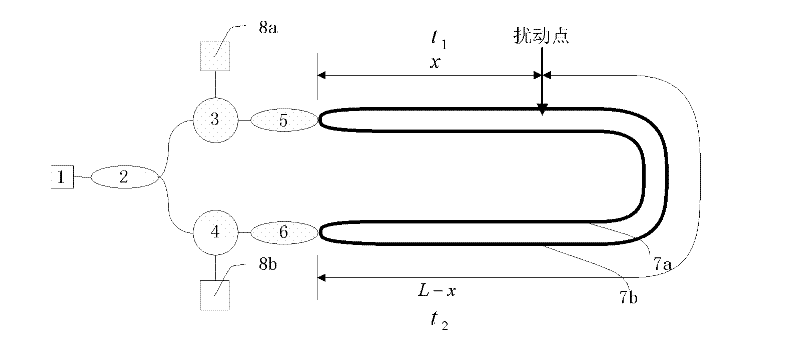
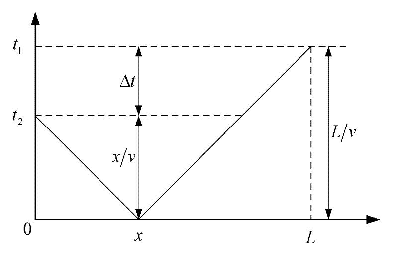
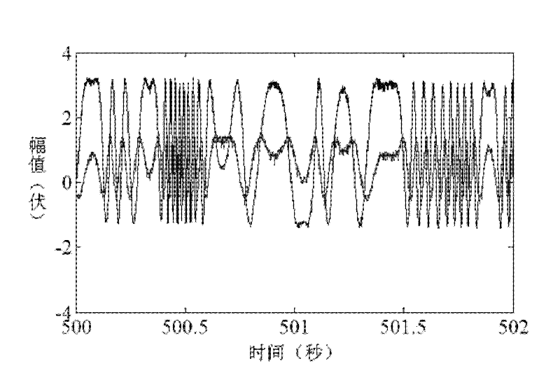
[0005] The purpose of the present invention is to solve the problem of inaccurate system positioning caused by the birefringence characteristics of the single-mode optical fiber in the existing method, and to provide a polarization control method and a polarization control system for an optical fiber perturbation system based on a simulated annealing algorithm. The polarization state of the signal light in one arm of the fiber optic vibration sensing system can keep the polarization state of the signal light in the two arms of the system as consistent as possible, thereby improving the positioning accuracy of the system

Method used


Image

  • Optical fiber disturbance system polarization control method and control system based on annealing algorithm
  • Optical fiber disturbance system polarization control method and control system based on annealing algorithm
  • Optical fiber disturbance system polarization control method and control system based on annealing algorithm

Examples


Embodiment 1

[0051] Embodiment 1: A polarization control system used in a distributed optical fiber disturbance location system

[0052] Such as Figure 5 As shown, the system includes:

[0053] Laser 9, first coupler 10, second coupler 13 and third coupler 14, first optical circulator 11 and second optical circulator 12, sensing optical cable 17, first photodetector 18a and second photoelectric Detector 18b.

[0054] Squeeze-type polarization controller 15: It has four squeezers arranged staggered at 45° in extrusion directions. The first two fiber squeezers are used in the control process, and different combinations of voltages can be applied to the two squeezers. The polarization states of the input light waves are modulated differently to output light waves of different polarization states. Add a polarization controller to one of the sensing fibers of the basic distributed optical fiber sensing system, and realize polarization control by modulating the polarization state of the opti...

Embodiment 2

[0059] Embodiment 2: Polarization control method

[0060] One of the important conditions for two beams of light to interfere is that the light participating in the interference is linearly polarized and has the same polarization direction. The positioning algorithm of the distributed optical fiber disturbance location system is based on the assumption that linearly polarized light interferes with the same polarization direction.

[0061] Distributed optical fiber disturbance positioning system is mainly used for perimeter protection, earthquake monitoring, etc. The optical fiber used is tens of kilometers or even hundreds of kilometers long. If the polarization maintaining optical fiber and its corresponding supporting components are used, it will be very expensive. Considering the cost, the system The sensing fibers used are all commonly used single-mode fibers.

[0062] Ordinary single-mode fiber due to random factors such as geometric bending, ambient temperature changes, ...


PUM


Abstract

The invention discloses an optical fiber disturbance system polarization control method and control system based on an annealing algorithm. In the polarization control, an analogue annealing algorithm is used as a control algorithm, and a polarization controller is used for modulating an interference optical wave polarization state. The relevance between two interference signals received by a detector in a distributed optical fiber disturbance positioning system is used as a feedback signal, and the analogue annealing algorithm is used for searching an extra voltage of a corresponding polarization controller when the difference between signals is the smallest. The polarization control system comprises a continuously distributed optical fiber sensing system based on dual Mach-Zehnder optical fiber interferometer, an extrusion type polarization controller, a LiNbO3 birefraction phase modulator, a singlechip system, a computer and algorithm software. The optical fiber disturbance system polarization control method provided by the invention can effectively improve the anti-polarization induced fading ability of the system by controlling the polarization state of the interference light, and can greatly eliminate the influence of the single-mode optical fiber birefraction to the system positioning precision.

Description

technical field [0001] The invention belongs to the technical field of sensing and detection. Background technique [0002] With the development of science and technology and the enhancement of people's security awareness, it has become a necessary and urgent problem to develop a perimeter security system with large detection range, low energy consumption and low cost. Due to its high sensitivity, anti-electromagnetic interference, and no power supply, the distributed optical fiber vibration sensing system has been widely used in military defense, financial protection, energy security, community security and other security fields, and will have a wide range of applications in the future. application prospects. [0003] One of the necessary conditions for light waves to interfere is that the light vectors participating in the interference have the same vibration direction, that is, they have the same polarization direction components. The optical fiber used in the actual pe...

Claims


Application Information

Patent Timeline
IPC IPC(8): H04B10/12G02F1/01H04B10/2569
Inventor 刘铁根刘琨江俊峰丁振扬陈沁楠孙巍张笑平李定杰
Owner TIANJIN UNIV
Learn More