
High temperature methanation device

A methanation and high-temperature technology, applied in organic chemistry, hydrocarbon production from carbon oxides, chemical instruments and methods, etc., can solve the problems of strict requirements for pipeline materials and connection structures, overheating of by-products, large equipment footprint, etc.

Active Publication Date: 2012-06-27
CHINA PETROLEUM & CHEM CORP +2
View PDF4 Cites 2 Cited by
  • Summary
  • Abstract
  • Description
  • Claims
  • Application Information

AI Technical Summary

Problems solved by technology

In the prior art, the methane synthesis reactor, the steam generator, the waste pot and the superheater are arranged separately, which brings about two problems: first, the temperature of the reaction gas is as high as 600°C, if the superheater is placed before the waste pot, High-pressure steam can be produced by-product, but due to the high temperature and pressure, it is difficult to select and manufacture the steam superheater
Therefore, the steam superheater is usually placed behind the waste pot. Such a process setting often leads to insufficient steam superheat, or only superheated medium-pressure steam is produced by-product, resulting in the high-temperature waste heat of the process gas not being well utilized. unreasonable
Second, it is difficult to guarantee the reliability and safety of the connection between the methanation reactor, the steam superheater, and the waste pot using ordinary process pipes. Even if the pipe connection is used, there are strict and demanding requirements on the material and connection structure of the pipes. Requirements, high engineering investment costs
The third is the existing process equipment, the equipment occupies a relatively large area

Method used


Image

  • High temperature methanation device
  • High temperature methanation device
  • High temperature methanation device

Examples


Embodiment Construction

[0018] The present invention will be further described in detail below in conjunction with the accompanying drawings and embodiments.

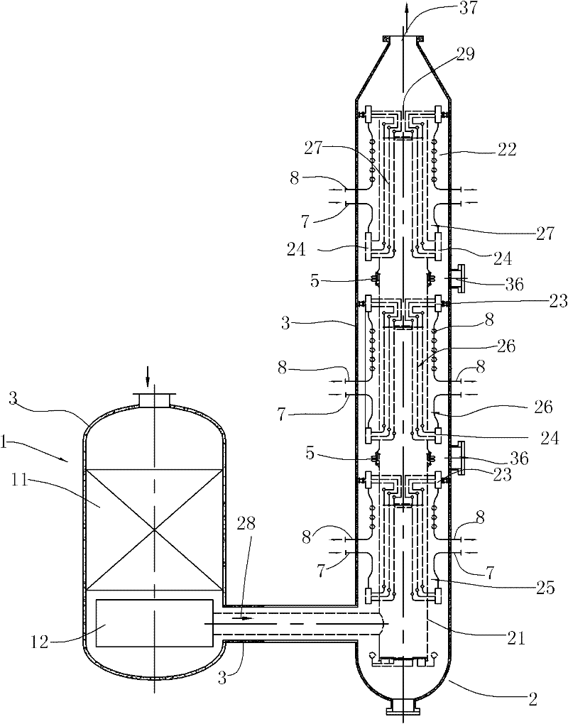
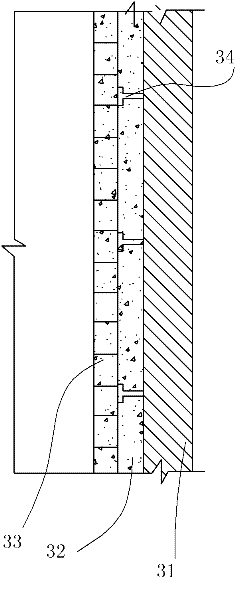
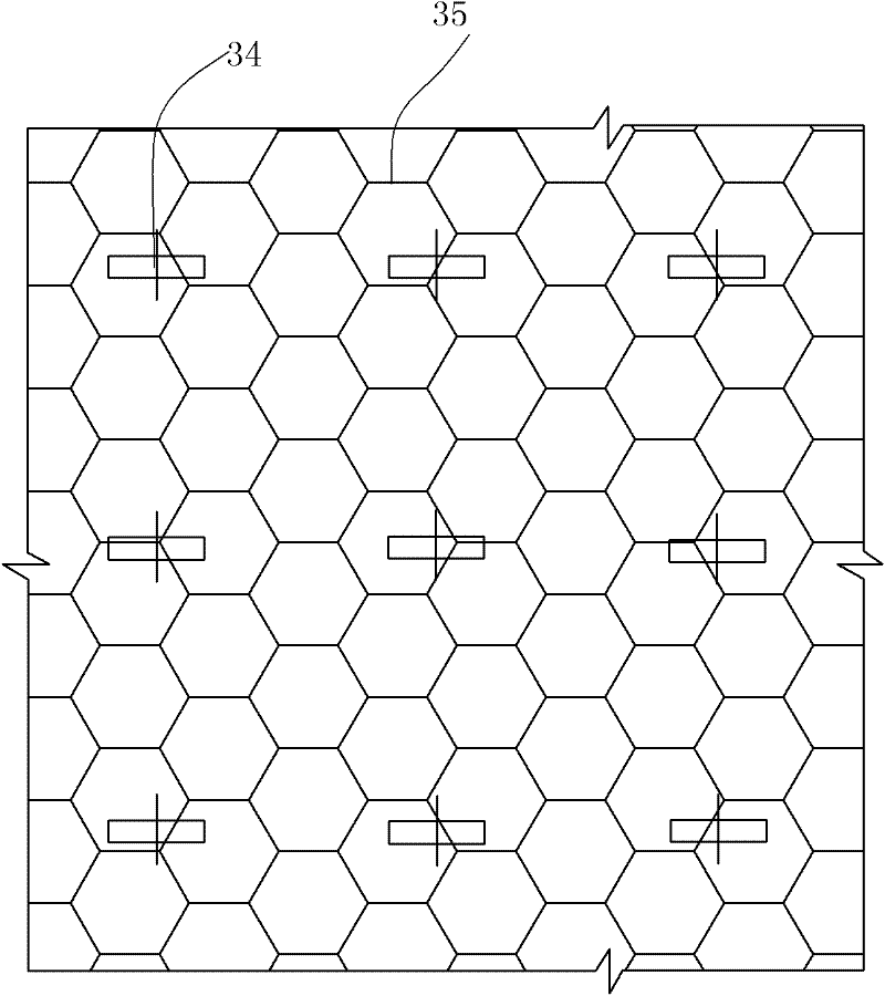
[0019] like Figure 1 to Figure 6 As shown, the high temperature methanation unit includes:

[0020] The methane reactor 1 mainly includes two parts, namely a catalyst layer 11 and a gas collector 12 arranged below the catalyst layer 11 . The methanation reactor in this embodiment is a vertical cylindrical vessel, the shell wall is covered with refractory and heat-insulating lining, and the middle part is filled with catalyst. The structure of the methane reactor is prior art.

[0021] The heat exchanger 2 is a vertical structure with three sections. Each section of the heat exchanger in this embodiment adopts a membrane-type water-cooled wall structure, which includes a cylinder 21 for the passage of the heat medium, that is, the process gas. Each layer of water-cooled walls in the cylinder body 21 and an upper header 23 and a lower header...


PUM

PropertyMeasurementUnit
thicknessaaaaaaaaaa
thicknessaaaaaaaaaa
thicknessaaaaaaaaaa

Abstract

The invention relates to a high temperature methanation device, which comprises a methane reactor for synthesizing methane and a heat exchanger for exchanging heat of gas exhausted by the methane reactor and is characterized in that the methane reactor and the heat exchanger are arranged in the same pressure container casing, a cooling device is arranged on a pipe, gas channels of all sections of the heat exchanger are sequentially in series connection through expansion joints with cooling devices, two ends of a cooling medium channel of each section of the heat exchanger are respectively connected with an corresponding upper collection tank and a corresponding lower collection tank, all sections of the heat exchanger are suspended in the casing through connection between drainage channels and the lateral wall of the casing and inlet channels and the lateral wall of the casing, and gaps are formed between each section of the heat exchange and the lateral wall of the casing at intervals. An outlet of the air channel of the hat exchange is communicated with an outlet of the casing. The methanation device is directly connected with a steam generation system. A waste pot and a superheater in the steam generation system are integrated, thereby resolving the problem that a steam generator and a steam superheater are difficult to choose in type.

Description

technical field [0001] The invention relates to the field of chemical equipment, in particular to a high-temperature methanation device. Background technique [0002] For the application of high-temperature methanation reaction in engineering, one of the core technologies is to solve the problem of removal and recovery of a large amount of reaction heat brought about by high CO content and rapid reaction, that is, the comprehensive utilization of reaction heat. In the prior art, the methane synthesis reactor, the steam generator, the waste pot and the superheater are installed separately, which brings about two problems: first, the temperature of the reaction gas is as high as 600°C, if the superheater is placed before the waste pot, High-pressure steam can be produced as a by-product, but due to the high temperature and pressure, the selection and manufacture of steam superheaters are difficult to achieve. Therefore, the steam superheater is usually placed behind the waste...

Claims


Application Information

Patent Timeline
Patent Type & Authority Applications(China)
IPC IPC(8): B01J8/02C07C1/10C07C9/04
Inventor 章晨晖亢万忠宋燕郭文元李晓黎杨宏泉陈央张炜王爱平张丽
Owner CHINA PETROLEUM & CHEM CORP
Learn More