Series diode circuit

A diode and circuit technology, applied in the field of series diode circuits, can solve problems such as difficulty in selecting compensation capacitors, and achieve the effect of reducing the difficulty of selection and solving the difficulty of selection.

Pending Publication Date: 2020-02-04
SHANGHAI UNITED IMAGING HEALTHCARE
View PDF7 Cites 0 Cited by
  • Summary
  • Abstract
  • Description
  • Claims
  • Application Information

AI Technical Summary

Problems solved by technology

[0011] Based on this, the present application provides a series diode circuit to at least solve the problem of difficult selection of the compensation capacitance of the series diode circuit in the related art

Method used


Image

  • Series diode circuit
  • Series diode circuit
  • Series diode circuit

Examples


Embodiment Construction

[0035] In order to make the purpose, technical solution and advantages of the present application clearer, the present application will be further described in detail below in conjunction with the accompanying drawings and embodiments. It should be understood that the specific embodiments described here are only used to explain the present application, and are not intended to limit the present application. Based on the examples in this application, all other examples obtained by persons of ordinary skill in the art without making creative efforts belong to the scope of protection of this application.

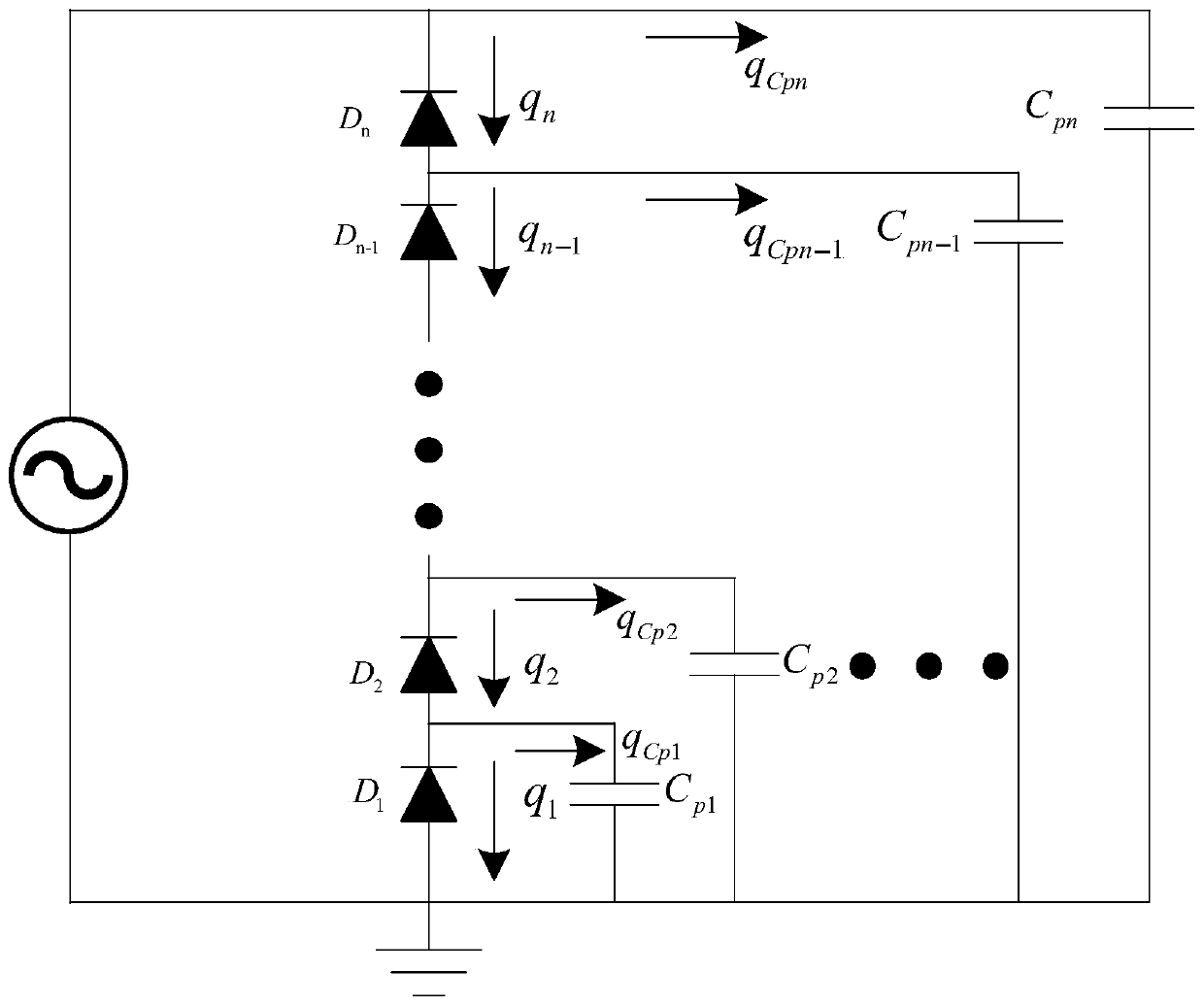
[0036] In this embodiment a series diode circuit is provided, image 3 is a schematic structural diagram of a series diode circuit according to an embodiment of the present invention, such as image 3 As shown, the series diode circuit includes: a first PCB board 1, a plurality of diodes 2, a plurality of diodes 2 are arranged on the first PCB board 1, and a plurality of diodes...


PUM


Abstract

The invention provides a series diode circuit. The series diode circuit comprises a first PCB and a plurality of diodes, the plurality of diodes are arranged on the first PCB, and the plurality of diodes are sequentially connected in series through a plurality of first wires laid on the first PCB; the series diode circuit further comprises a plurality of second wires which are laid on different layers from the first wires, and the second wires are used for generating parasitic capacitance so as to carry out voltage-sharing compensation on the series diode circuit. According to the invention, the problem that the compensation capacitor of the series diode circuit is difficult to select in the prior art is solved, and the selection difficulty of the compensation capacitor of the series diodecircuit is reduced.

Description

technical field [0001] The invention relates to the technical field of circuits, in particular to a series diode circuit with a voltage equalizing function. Background technique [0002] The diode is one of the basic components in many high-voltage generating circuits. Due to the limitation of the manufacturing process, the withstand voltage of a single diode cannot be made too high. Therefore, in practical applications, in order to generate higher voltages, multiple diodes in series are often used. way, but due to the existence of parasitic capacitance, it will cause uneven voltage of series diodes. Such as figure 1 Shown, C p1 、C p2 …C pn is the parasitic capacitance of each node of the diode to the ground, with D 2 For example, flow through D 2 The charge is q 2 =q 1 +q Cp =v 1 C D +v 1 C p1 , where v 1 is D 1 voltage across both ends, C D is the junction capacitance of the diode, it can be seen that due to the parasitic capacitance C p1 effect, resulting...

Claims


Application Information

Patent Timeline
Patent Type & Authority Applications(China)
IPC IPC(8): H03K17/56H05K1/18
CPCH03K17/56H05K1/18
Inventor 柳玉锋
Owner SHANGHAI UNITED IMAGING HEALTHCARE
Why Eureka
Try Eureka