Control method for flying shear tail-shearing of rod wire

A control method, bar and wire rod technology, applied in the direction of metal rolling, manufacturing tools, metal rolling, etc., can solve the problems of unable to complete the shearing normally, shorten the construction period, etc., and achieve stable and reliable shearing, shorten the construction period, and save costs. Effect

Inactive Publication Date: 2012-06-27
WISDRI WUHAN AUTOMATION
View PDF4 Cites 26 Cited by
  • Summary
  • Abstract
  • Description
  • Claims
  • Application Information

AI Technical Summary

Problems solved by technology

[0004] The technical problem to be solved by the present invention is to provide a method for controlling the flying shears of rods and wires. This method only adds a hot metal detector in front of the upstream rolling mill, and solves the problem of The layout of the upstream rolling mill and flying shears is too compact, and the distance between the hot metal detector and the cutting centerline of the flying shears is too short, so the tail cutting cannot be completed normally, which not only saves costs, but also shortens the construction period

Method used


Image

  • Control method for flying shear tail-shearing of rod wire
  • Control method for flying shear tail-shearing of rod wire
  • Control method for flying shear tail-shearing of rod wire

Examples


Embodiment Construction

[0034] The present invention will be further described below in conjunction with the embodiments and accompanying drawings.

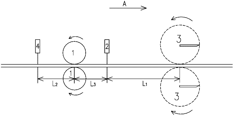
[0035] The rod and wire flying shears tail cutting control method provided by the present invention is an advanced electrical control method for rods and wires flying shears, specifically: through precise cutting edge position control, precise tail length control, second hot metal detector The conversion of the equivalent distance to the center line of the flying shear, the actual measurement and compensation of the elongation of the upstream rolling mill are combined to realize the short distance from the flying shear of the rod and wire to the first hot metal detector to the center line of the flying shear Timed tail-cutting control.

[0036] The tail cutting control method of the rod and wire provided by the invention comprises the steps of:

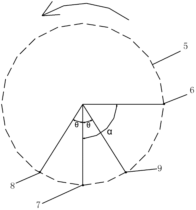
[0037] 1. Precise cutting edge position control

[0038] 1. An absolute encoder is installed at the end of...


PUM


Abstract

The invention relates to a control method for flying shear tail-shearing of rod wire. Specifically, when over compact arrangement of an upstream rolling mill (1) and the flying shear results in an over short distance from a first hot metal detector (2) to a shearing central line of the flying shear which does not allow normally shearing tail, a second hot metal detector (4) is additionally arranged in front of the upstream rolling mill (1); and the tail-shearing control, when the distance from the rod wire flying shear to the first hot metal detector (2) is over short, is realized by combining precise shear blade position control, precise shear tail length control, conversion of equivalent distance from the second hot metal detector (4) to the flying shear center line, actual measurement and compensation of elongation rate of the upstream rolling mill (1). The invention solves the problem that the tail-shearing project is not normally finished because of over compact arrangement of the upstream rolling mill (1) and the flying shear and over short distance from the first hot metal detector (2) and the flying shear in the rod wire production wire; and the tail-shearing is steady and reliable according to the actual application result.

Description

technical field [0001] The invention relates to the field of electrical control, in particular to a control method for tail cutting of flying shears for rods and wires. Background technique [0002] In the hot continuous rolling bar production line and high-speed wire rod production line, flying shear is the key equipment to improve the productivity and finished product rate of the rod and wire rod production line. At present, the flying shears on the rod and wire production line all adopt fully digital electric control start-stop flying shears (including rotary type, crank-connecting rod type, crank-connecting rod flywheel type). The main technological functions of flying shears are: cutting the head, cutting the tail, double-length cutting, breaking, etc. During the rolling process, the tail of the rolled piece is easy to crack, which affects the product quality. key process functions. [0003] In the actual project application, in order to save the floor area of ​​the f...

Claims


Application Information

Patent Timeline
Patent Type & Authority Applications(China)
IPC IPC(8): B21B15/00
Inventor 王胜勇陈启江卢家斌李传涛李四川李海东
Owner WISDRI WUHAN AUTOMATION
Why Eureka
Try Eureka