Corrugation pipe cutting machine

A technology of pipe cutting machine and corrugation, applied in the field of corrugated pipe cutting machine, can solve the problems of tool post guidance, inaccurate positioning, feeding length error, inaccurate feeding, etc., to achieve uniform force, small feeding length error, tool post accurate positioning

Inactive Publication Date: 2012-06-27
临沂英伯数控机械有限公司
View PDF13 Cites 5 Cited by
  • Summary
  • Abstract
  • Description
  • Claims
  • Application Information

AI Technical Summary

Problems solved by technology

[0002] Corrugated pipes are widely used in industry today, and can be used in drainage and ventilation pipes of mines and buildings; chemical ventilation pipes and chemical and mine fluid delivery pipes; high-voltage cables, post and telecommunications cable protection casings, etc. A special machine (corrugated pipe cutting machine) cuts it into a certain length. The feeding mechanism of the traditional corrugated pipe cutting machine mainly adopts the structure of several feeding wheels that are in rolling friction contact with the pipe fittings. The friction generated by the pipe makes the pipe move forward to complete the feeding process. During the above feeding process, the feeding wheel is in contact with the pipe at a tangential point, which leads to problems such as large feeding length error, inaccurate feeding, and instability.
[0003] The cutter mechanism of the traditional corrugated pipe cutting machine adopts a cylinder structure, which needs to be distributed with compressed air source, so the cost is high; and its cutting force is small, the action is slow, so the efficiency is low; the knife of the cutter mechanism of the traditional corrugated pipe cutting machine Rack guidance, inaccurate positioning and other issues

Method used


Image

  • Corrugation pipe cutting machine
  • Corrugation pipe cutting machine
  • Corrugation pipe cutting machine

Examples


Embodiment Construction

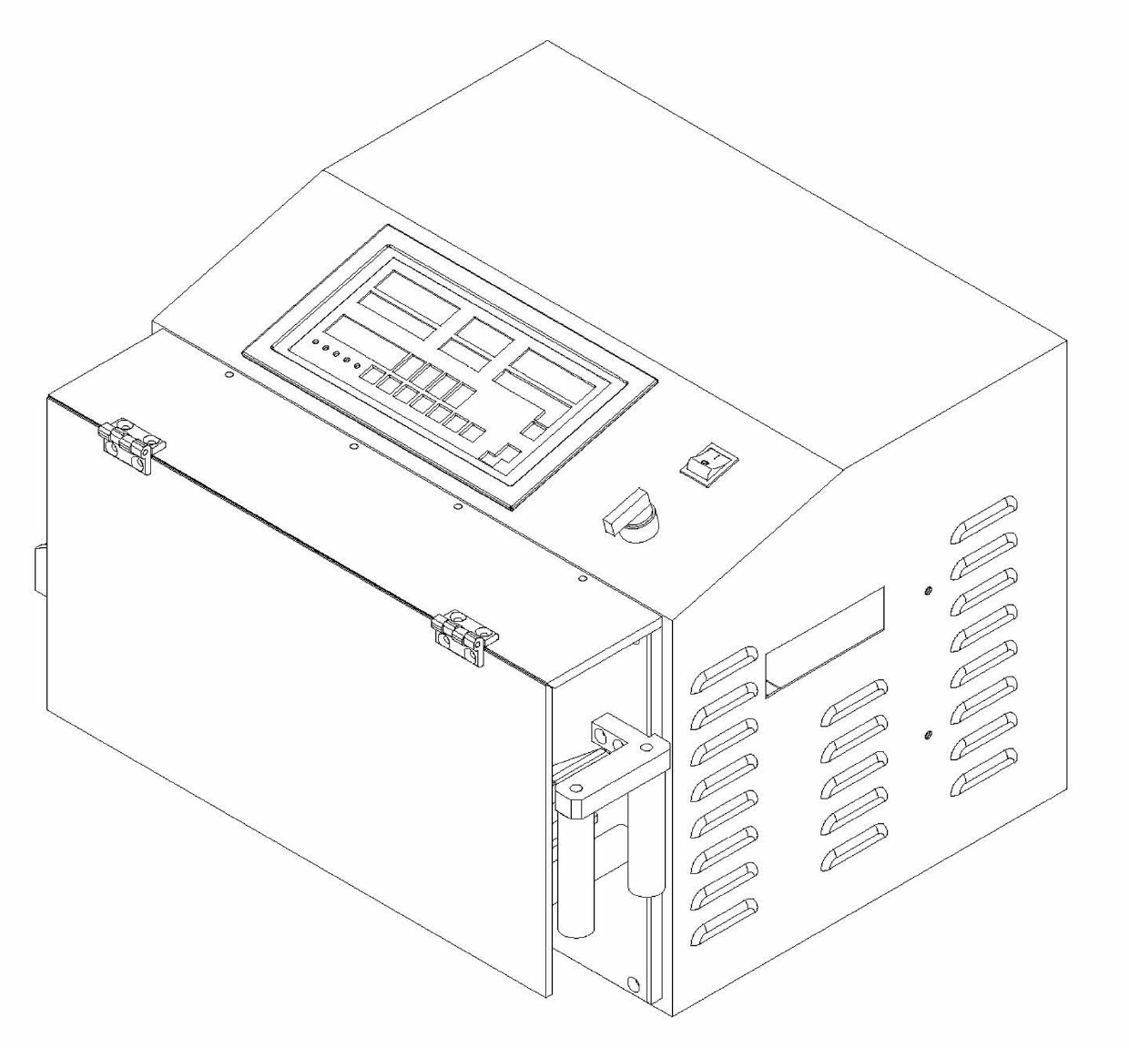
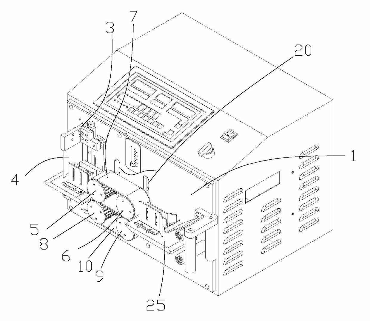
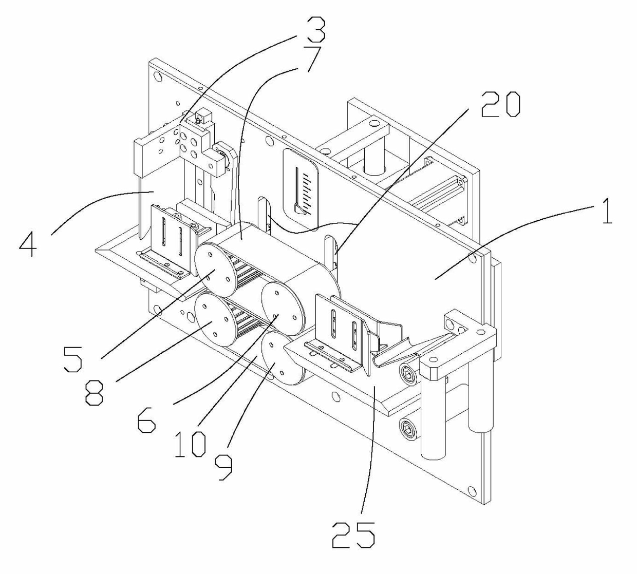
[0033] refer to Figure 1 to Figure 7 , the invention discloses a corrugated pipe cutting machine, comprising a frame 1, a cutter mechanism capable of cutting pipe materials, a feeding mechanism capable of feeding pipe materials into the cutter mechanism, a feed wheel gap adjustment mechanism and a control mechanism are arranged on the frame 1. mechanism, the feeding mechanism includes an upper pulley set, a lower pulley set, a first drive mechanism and a first transmission mechanism connected to the power output end of the first drive mechanism, the upper pulley set and the lower pulley set and The first transmission mechanism is connected, and the gap between the upper pulley set and the lower pulley set can be adjusted by the gap adjustment mechanism of the feeding wheel, and the control mechanism is electrically connected with the feeding mechanism, the cutter mechanism and the gap adjustment mechanism of the feeding wheel, Described cutter mechanism comprises the lower cu...


PUM


Abstract

The invention discloses a corrugation pipe cutting machine, which comprises a frame which is provided with a cutting mechanism, a feed mechanism, a feed wheel gap adjusting mechanism and a control mechanism. The feed mechanism comprises an upper belt wheel group, a lower belt wheel group, a first driving mechanism and a first transmission mechanism connected with the power output end of the first driving mechanism. The upper belt wheel group and the lower belt wheel group are connected with the first transmission mechanism, a gap between the upper belt wheel group and the lower belt wheel group can be adjusted through the feed wheel gap adjusting mechanism, and the control mechanism is electrically connected with the feed mechanism, the cutting mechanism and the feed wheel gap adjusting mechanism. The cutting mechanism comprises a lower cutter arranged on the frame and a second driving mechanism, the power output end of the second driving mechanism is connected with a connecting rod mechanism, an upper cutter seat is connected onto the connecting rod mechanism, the upper cutter seat is arranged on the frame through a guiding mechanism, and an upper cutter is arranged on the upper cutter seat which can drive the upper cutter and the lower cutter to cut through guide of the guiding mechanism.

Description

technical field [0001] The invention relates to a pipe cutting machine, in particular to a corrugated pipe cutting machine. Background technique [0002] Corrugated pipes are widely used in industry today, and can be used in drainage and ventilation pipes of mines and buildings; chemical ventilation pipes and chemical and mine fluid delivery pipes; high-voltage cables, post and telecommunications cable protection casings, etc. A special machine (corrugated pipe cutting machine) cuts it into a certain length. The feeding mechanism of the traditional corrugated pipe cutting machine mainly adopts the structure of several feeding wheels that are in rolling friction contact with the pipe fittings. The friction generated by the pipe makes the pipe move forward to complete the feeding process. During the above feeding process, the feeding wheel and the pipe are in tangential contact, which leads to large errors in feeding length, inaccurate feeding, and instability. [0003] The c...

Claims


Application Information

Patent Timeline
IPC IPC(8): B26D1/08B26D7/06B26D5/18B26D7/26
Inventor 李业赵维王军平
Owner 临沂英伯数控机械有限公司
Why Eureka
Try Eureka