Method for molding composite material wind power blade root
A technology of wind turbine blades and composite materials, which is applied to other household appliances, household appliances, household components, etc., can solve the problems of composite materials without related patents and reports, and achieve the effects of shortening the production cycle, improving the overall cost performance, and shortening the occupation time
- Summary
- Abstract
- Description
- Claims
- Application Information
AI Technical Summary
Problems solved by technology
Method used
Image

Examples
Embodiment 1
[0028] Application example of root forming of large composite wind power blade with a length of 50m and a width of 5m.
[0029] The root of the blade has a total of 120 layers, and 70 layers are prefabricated with small molds. The process description is as follows:
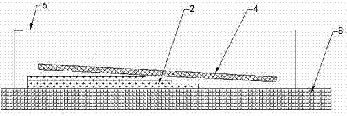
[0030] 1. Make a small mold at the root (0-3.6m);
[0031] 2. Lay the 40th to 110th layer of blades in a small mold;
[0032] 3. Lay auxiliary materials on the upper layer of the small mold layer;
[0033] 4. Establish a vacuum sealing system on the small mold;
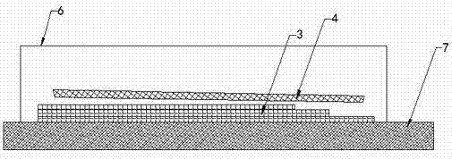
[0034] 5. Vacuum infusion molding and heat curing of 70 layers of small molds;
[0035] 6. Demoulding and saving the 70-layer prefabricated body of the small mold;
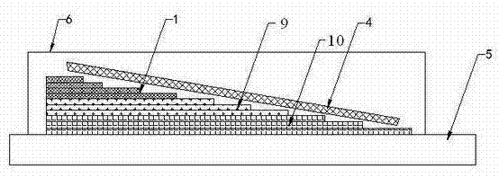
[0036] 7. Carry out the 1st to 39th layers of fiber laying in the molds of the lower shell and the upper shell of the blade;
[0037] 8. Put the demolded prefabricated body into the shell mold;
[0038] 9. Continue to lay the 111th to 120th layers in the shell mold;
[0039] 10. The l...
PUM
 Abstract
Description
Claims
Application Information
PatSnap Eureka turns technology decisions into work you can execute. Powered by our Innovation Knowledge Graph, it runs expert workflows across engineering, life sciences, materials and intellectual property. Get your review-ready output in minutes.


