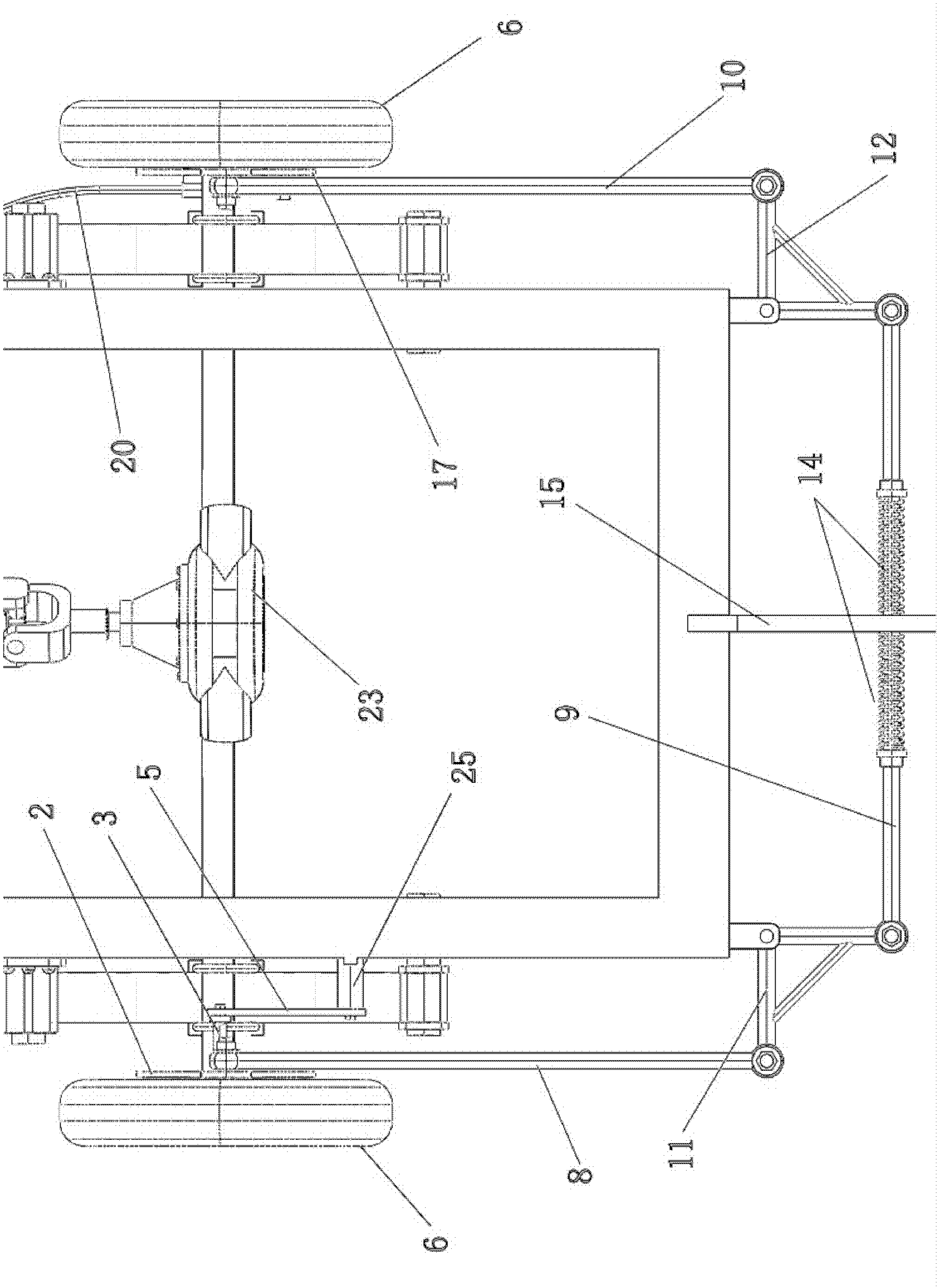
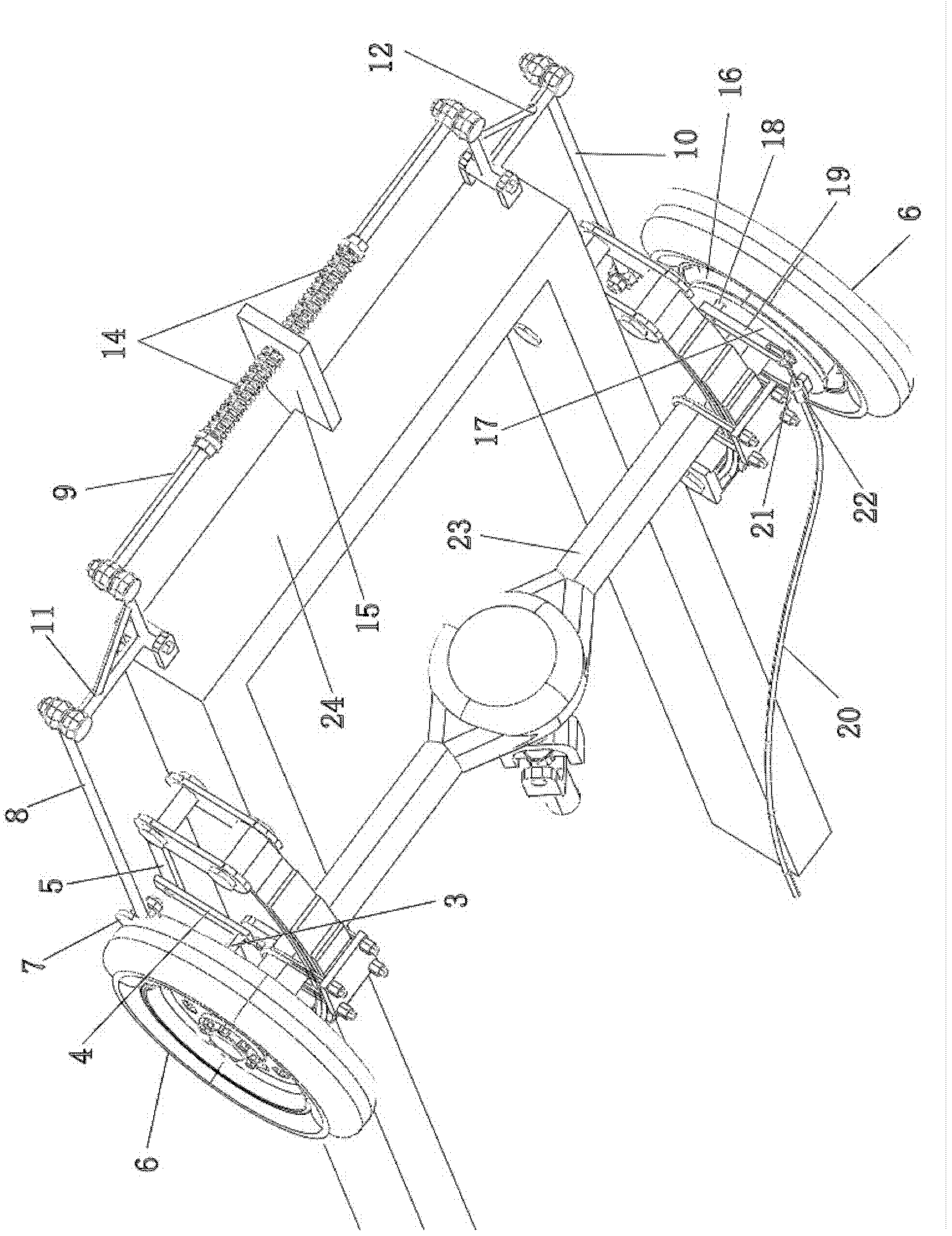
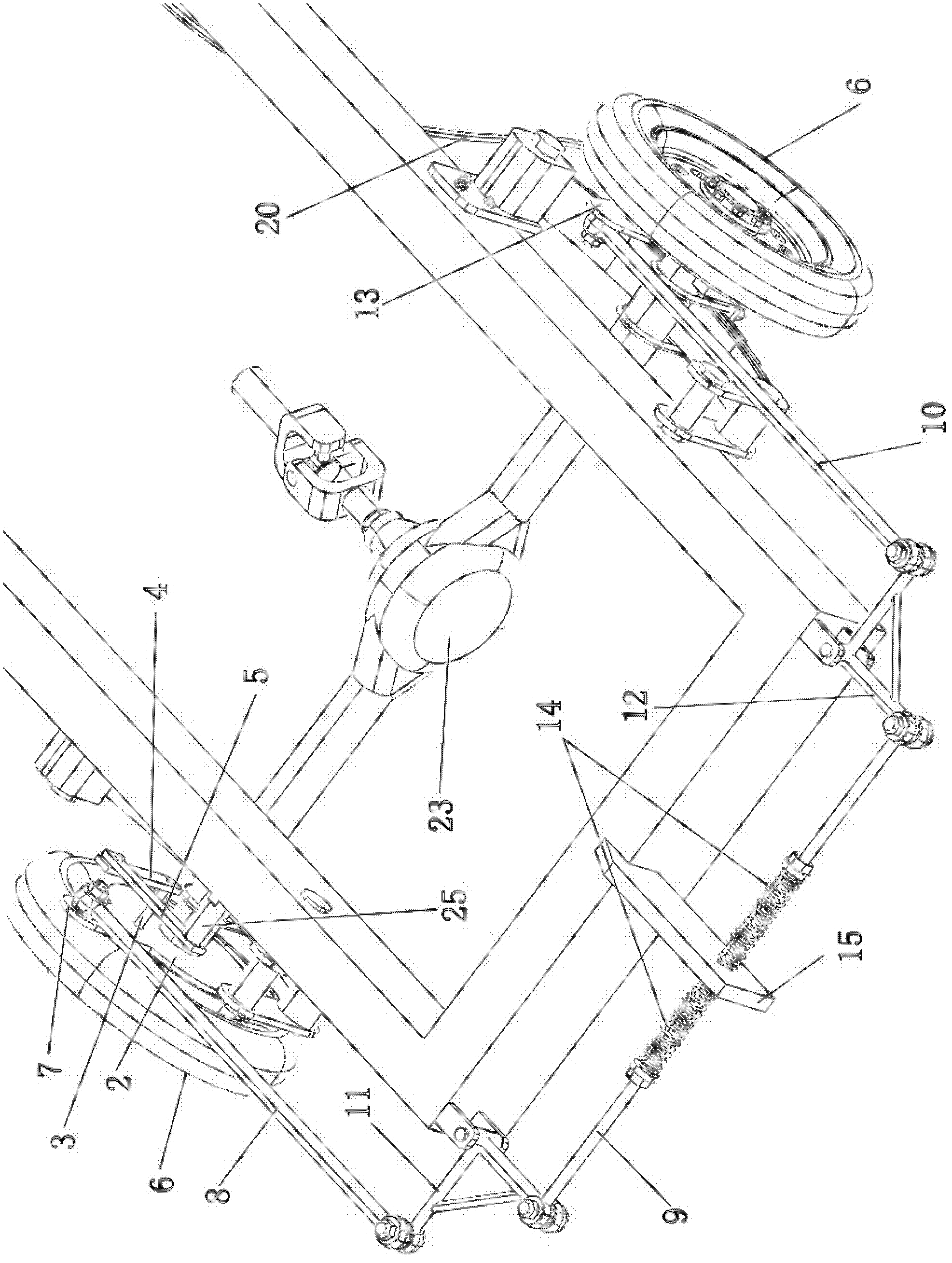
[0010] Working principle: When the drum brake device is braking, the brake drum will drive the shoe disc to rotate through the brake shoe. The shoe disc must provide enough reaction force to the brake shoe to achieve effective braking. The braking force of the drum brake depends on the pressure in the sub-cylinder or the rotation angle of the camshaft and the rocker arm. This solution is to use these two bumps to movably install the left and right hoof discs on the rear axle or drive shaft so that it can rotate freely. At the same time, the two hoof discs are connected by a transmission device so that they can be reversed synchronously. Rotating in the direction of rotation, one braking device drives the other braking device to rotate and brake. The transmission device mentioned here can be constituted by a connecting rod or a chain or the like. In this example, the rear wheel 6, the right camshaft 18 and the right rocker arm 19 on the right shoe plate 17 are controlled by the driver's brake pedal through the brake wire 20 and the brake rope 21. The left camshaft 3 and the left rocker arm 4 on the left shoe plate 2 of the brake device of the other rear wheel (the left rear wheel in this example) are hinged on the support 25 of the frame through the brake link 5. When the left shoe plate 2 rotates at a certain angle, the left camshaft 3 also rotates at the same angle to generate a certain braking force. When the right rear wheel brakes, the reaction force on the right shoe plate 17 is provided by the left shoe plate 2 on the other rear wheel, that is to say, the left and right rear wheels use their own braking force for the other. The rear brake device increases the reaction force. As long as the braking devices of the left and right rear wheels are strictly symmetrical, theoretically the braking forces obtained by the two rear wheels are automatically and strictly equal, and they are in a dynamic equilibrium state. At the same time, the brake pedal only applies braking to one of the rear wheel brake devices to achieve simultaneous braking of the two rear wheels, which improves the braking sensitivity and achieves two effects. It should be particularly noted that this technical solution is not only applicable to tricycles but also to four-wheeled vehicles.
[0011] In this example, the left and right rear wheels are equipped with basically the same drum brake device. The brake device on the right rear wheel is mainly composed of the right brake drum 16, the brake shoe, the right shoe 17, and the right The camshaft 18, the right rocker 19 and other components. The braking device on the left rear wheel is mainly composed of the left brake drum 1, the brake shoe, the left shoe plate 2, the left camshaft 3, the left rocker arm 4 and so on. Both the left and right hoof plates are welded with hoof plate lugs integrated with the hoof plate. The right shoe plate 17 is welded with a right shoe plate lug 13 and a brake wire bracket 22. The right shoe plate lug 13 is connected to the left shoe plate lug 7 through the right connecting rod 10, the right lever 12, the middle connecting rod 9, the left lever 11, and the left connecting rod 8. These connecting rods, levers, and lugs all pass The end rod joint bearings are hinged together, the left lever 11 and the right lever 12 are hinged on the frame 24 as figure 1 , figure 2 Shown. In this way, the left shoe plate 2 and the right shoe plate 17 can realize synchronous reverse rotation. A brake wire 20 is installed on the right shoe plate, which is fixed on the right shoe plate 17 through a brake wire bracket 22, and a brake cable 21 on the brake wire is installed on the right rocker arm 19. The other end of the brake wire is connected to the driver's brake pedal. When the driver steps on the brake pedal, the brake rope 21 on the brake wire drives the right rocker arm 19 and the right camshaft 18 to rotate, driving the brake shoe to brake the right brake drum 16 and the right rear wheel. The right rear wheel drives the right brake drum 16, the brake shoe, and the right shoe disc 17 to rotate. When the right shoe plate 17 rotates, the left shoe plate 2 is driven to rotate in the reverse direction through the above-mentioned transmission device. The left camshaft 3 on the left shoe plate 2 is fixedly installed with a left rocker arm 4, the left rocker arm 4 is hinged with a brake link 5, and the other end of the brake link 5 is hinged on a support 25. Since one end of the left rocker arm 4 is relatively fixed to the support 25 through the brake link 5, as long as the left shoe plate 2 rotates a certain angle, the left cam shaft 3 also rotates the same angle and drives the brake shoe to brake the left Drum 1, the left rear wheel applies braking. The braking force of the right rear wheel only depends on the driver's effort, it has nothing to do with the turning angle of the right shoe disc 17, and the braking force of the left rear wheel only depends on the turning angle of the left shoe disc 2. Since the two are connected in opposite directions, the right shoe plate 17 can exchange its rotation angle for the reaction force it needs, that is to say, the larger its rotation angle, the greater the reaction force obtained. The left shoe 2 just needs a corner to generate the braking force, and the two shoe disks are in a complementary relationship in series to produce dynamic balance during braking. When the driver stepped on the brake pedal more vigorously, the driving force of the right rear wheel to the right shoe plate 2 increased. The original balance on the right hoof plate 2 is broken. The right shoe plate 2 rotates. The rotation of the left shoe plate 17 through the transmission device also produces synchronous and reverse rotation. The rotation of the left shoe plate 17 increases the friction between it and the left brake drum, so that the left shoe plate 17 A greater reaction force is produced to resist the continuation of this rotation. This creates a new balance. This braking system can make the left and right rear wheels get exactly the same braking force. At the same time, the brake pedal only brakes one of the left and right wheels. With one braking force, the two wheels can get the same amount at the same time. Brake. This is very precious to a motor tricycle, it can effectively avoid the deviation and rollover that are easy to occur during braking. In this system, a return spring 14 and a spring bracket 15 are installed on the middle link 9. When braking, the middle lever 9 is pulled to one side, and the spring on this side is compressed. After braking, the spring return lever is pushed back to its original position.
[0012] The brake cable 20 and brake tension 21 in this example can also be installed on the left shoe plate 2 to brake the left brake drum and the left rear wheel. The left rocker arm 4 and the brake link on the left shoe plate 2 5. The support 25, etc. are mirrored on the right shoe plate 17 and the right side of the frame as they are. In short, the brakes on the left and right sides are exchanged, and the effect is exactly the same. In addition to the brake wire in this example, the driver can also use an oil pump to brake the wheels. For example, the master cylinder is installed on the brake pedal, and the sub-cylinder is installed on the right shoe 17 or left shoe 2 to drive the brake. The shoe brakes the corresponding brake drum and rear wheel. The master cylinder and the sub-cylinder are connected by oil pipes, and together with the right or left brake drum, etc., it can also form a braking device. The left shoe plate 2 and the right shoe plate 17 can also be connected by a transmission device formed by a chain, such as Figure 5 Shown. The four sprocket wheels 28 are fixed on the frame 24 through four sprocket brackets 26, and the left shoe plate lug 7 and the right shoe plate lug 13 are connected together by a chain 27. Make them rotate in the reverse direction, except for the same as the previous example. As long as the left shoe plate 2 and the right shoe plate 17 can produce reverse synchronous rotation, any transmission device is suitable for use in this technical solution.