Method for adjusting poses of airplane components based on 3-2-1 following locator

A technology for adjusting aircraft parts and poses, applied to aircraft parts, aircraft assembly, ground installations, etc., can solve problems such as waste, increased production costs, and systems that cannot be reused

Inactive Publication Date: 2012-06-27
NANJING UNIV OF AERONAUTICS & ASTRONAUTICS +1
View PDF6 Cites 16 Cited by
  • Summary
  • Abstract
  • Description
  • Claims
  • Application Information

AI Technical Summary

Problems solved by technology

If a full-degree-of-freedom system is used, it is necessary to redesign and manufacture a new system

Method used


Image

  • Method for adjusting poses of airplane components based on 3-2-1 following locator
  • Method for adjusting poses of airplane components based on 3-2-1 following locator
  • Method for adjusting poses of airplane components based on 3-2-1 following locator

Examples


Embodiment

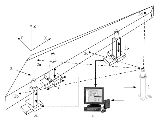
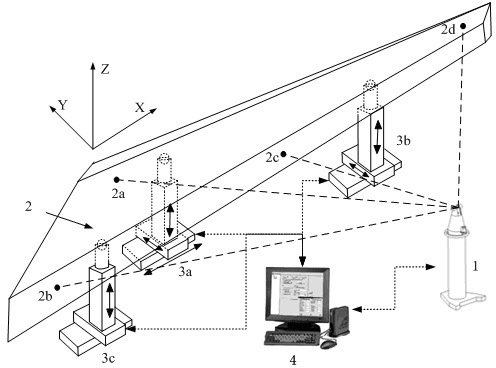
[0063] Such as figure 1 As shown, a method for adjusting the pose of an aircraft component based on a 3-2-1 follow-up locator includes the following steps:

[0064] Step 1. Place the aircraft component 2 to be adjusted on three three-degree-of-freedom positioners 3a, two-degree-of-freedom positioners 3b, and single-degree-of-freedom positioners 3c through the ball joint type process joint;

[0065] Step 2: Set four measuring points 2a, 2b, 2c, and 2d on the aircraft component to be adjusted, and use the laser tracker 1 to measure each measuring point to obtain the actual measured coordinate X of each measuring point a 、X b 、X c and x d ;

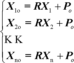
[0066] Step 3, control system 4 according to the measured coordinate X of the measuring point a 、X b 、X c 、X d and target coordinates X ao 、X bo 、X co 、X do Calculate the difference between the current space attitude of the aircraft component to be adjusted and the target attitude, that is, the space attitude angle adjustments α,...


PUM


Abstract

The invention discloses a method for adjusting poses of airplane components based on a 3-2-1 following locator, which comprises the following steps: firstly, calculating a difference between a current space pose and a target pose of the airplane components to be adjusted according to a measured coordinate and a target coordinate of a measuring point; setting N measuring points on the airplane components to be adjusted; then, calculating a difference between a current space position and a target position of the airplane components to be adjusted; and driving a three-degree of freedom locator, a two-degree of freedom locator and a single-degree of freedom to move according to the difference. The pose adjustment algorithm is simple and easy to implement; and has good adaptability, so that non-rigid body movement cannot occur in the pose adjustment process of the airplane components, and the safety of the pose adjustment process is ensured.

Description

technical field [0001] The invention relates to a method for adjusting the pose of an aircraft component, in particular to a method for adjusting the pose of an aircraft component based on a 3-2-1 follow-up locator. technical background [0002] The traditional docking assembly of large parts of the aircraft (docking of the front, middle and rear sections of the fuselage, wing and fuselage docking, etc.) uses manual positioners to support aircraft components and optically assisted positioning to adjust the pose of the components. Since this method completely relies on manual experience and manual operation, the labor intensity is high, the attitude adjustment efficiency is low, and the attitude adjustment accuracy is difficult to guarantee. In order to overcome the deficiencies of traditional attitude adjustment methods for aircraft components, combined with high-precision measuring equipment (laser tracking measuring instrument, indoor GPS or laser radar), and adopting auto...

Claims


Application Information

Patent Timeline
IPC IPC(8): B64F5/00B64F5/10
Inventor 黄翔陈磊李泷杲方伟
Owner NANJING UNIV OF AERONAUTICS & ASTRONAUTICS
Why Eureka
Try Eureka