Coiled material conveying and tensioning device

A tensioning device and tensioning technology, applied in the direction of winding strips, transportation and packaging, thin material processing, etc., can solve problems such as intricate rolls, affecting the progress of the production process, and tensioning effect of the tensioning device, achieving responsiveness Fast speed, avoiding the effect of poor guiding movement

Active Publication Date: 2012-06-27
CHERY AUTOMOBILE CO LTD
View PDF9 Cites 28 Cited by
  • Summary
  • Abstract
  • Description
  • Claims
  • Application Information

AI Technical Summary

Problems solved by technology

[0003] The known tensioning devices generally adjust the tension through the mechanical structure, such as adjusting the position of the tensioning roller through the screw pair, or through the swing arm. The structure is complex, the volume is huge, and the guide rollers are intricate, which easily leads to the guiding movement of the coil. It is not smooth, cannot be adjusted quickly and automatically in real time, and when used for a long time, the tensioning device will be worn and the tensioning effect will be reduced. The process of repairing and adjusting the tension is time-consuming and laborious, which will affect the progress of the entire production process.

Method used


Image

  • Coiled material conveying and tensioning device
  • Coiled material conveying and tensioning device
  • Coiled material conveying and tensioning device

Examples


Embodiment 1

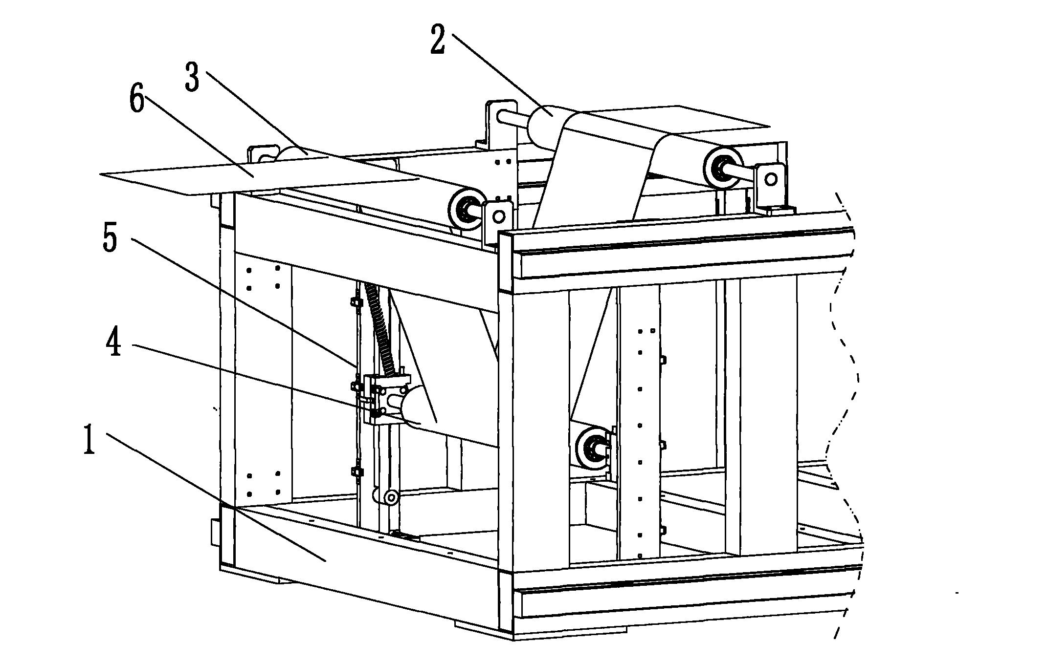
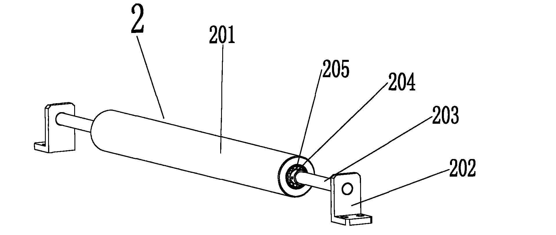
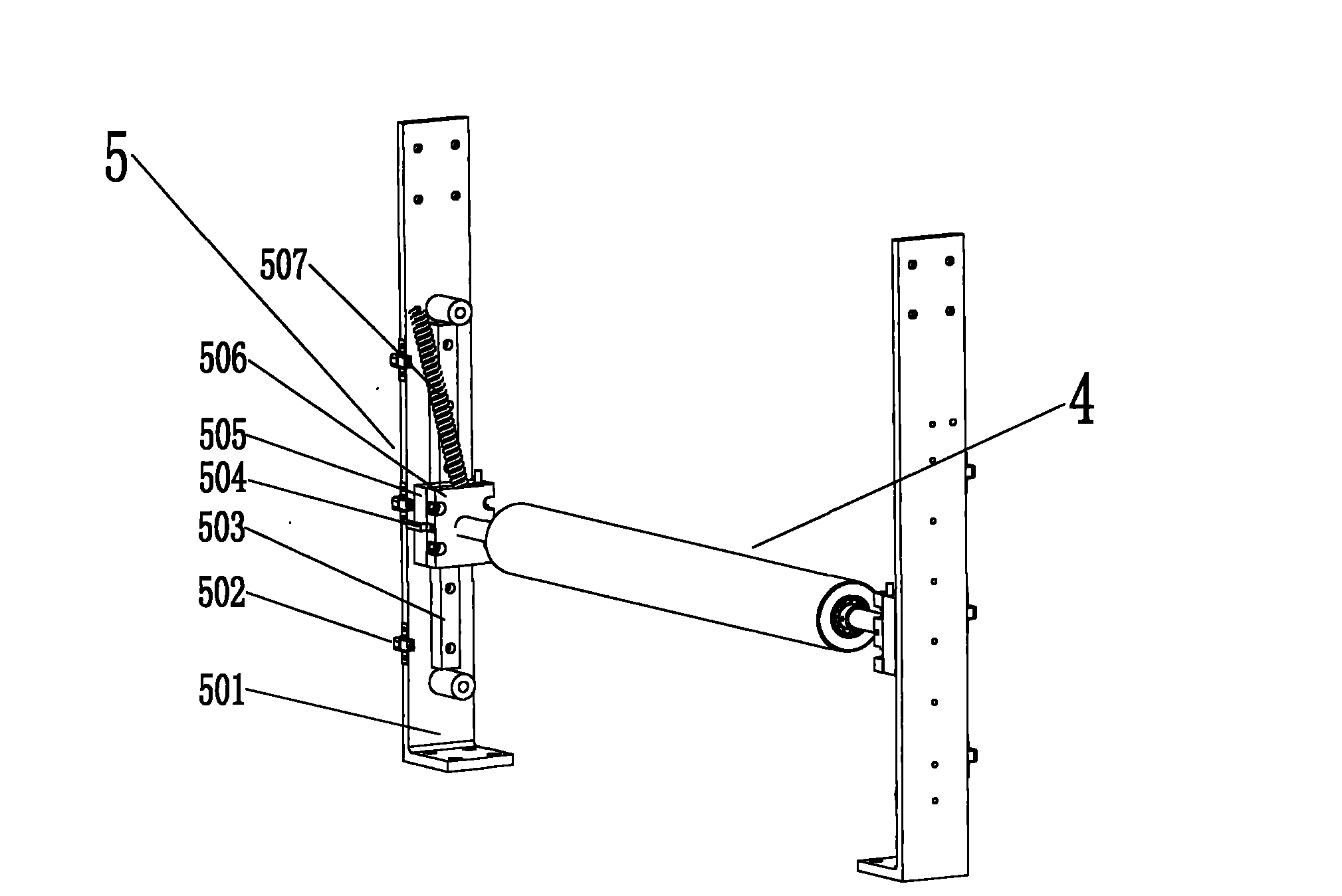
[0034] like figure 1 As shown, in this embodiment, the coil conveying tensioning device includes a workbench support 1 and a first guide roller assembly 2, a second guide roller assembly 3, and a tension guide roller assembly arranged on the workbench support 1. 4 and the tension guide roller bracket assembly 5, the first guide roller assembly 2 and the second guide roller assembly 3 are arranged on the upper part of the workbench bracket, and the tension guide roller bracket assembly 5 is arranged on the first Between the guide roller assembly 1 and the second guide roller assembly 2 , both ends of the tension guide roller assembly 4 are erected on the tension guide roller bracket assembly 5 . The axes of the first guide roller assembly 2 , the second guide roller assembly 3 and the tension guide roller assembly 4 are parallel.

[0035] The first guide roller assembly includes a first guide roller, the second guide roller assembly includes a second guide roller, the tension ...

Embodiment 2

[0051] The difference between this embodiment and Embodiment 1 is that there is no limit switch.

[0052] Other structures in this embodiment are the same as those in Embodiment 1, and will not be repeated here.

[0053] From the above detailed description of the embodiments of the present invention, it can be understood that the present invention solves the problems of complex tension structure and slow adjustment of coil tension in the conventional coil tensioning device. Advantages of adjusting tension.


PUM


Abstract

The invention discloses a coiled material conveying and tensioning device, which comprises a workbench support (1), and a first guide roller assembly (2), a second guide roller assembly (3), a tensioning guide roller assembly (4) and a tensioning guide roller support assembly (5) which are arranged on the workbench support, wherein the tensioning guide roller support assembly is arranged between the first guide roller assembly and the second guide roller assembly; the tensioning guide roller assembly is erected on the tensioning guide roller support assembly; the tensioning guide roller assembly is positioned below the first guide roller assembly and the second guide roller assembly; the first guide roller assembly comprises a first guide roller; the second guide roller assembly comprises a second guide roller; the tensioning guide roller assembly comprises a tensioning guide roller; and a coiled material passes through the first guide roller, the tensioning guide roller and the second guide roller in turn to reach a tension state. The coiled material conveying and tensioning device has a simple structure and has the advantages of high response speed and capacity of automatically adjusting the tension of the coiled material at a feed end.

Description

technical field [0001] The invention relates to a coil conveying tensioning device. Background technique [0002] At present, large-scale coil processing machines such as general coating machines, film laminating machines, and compound machines are generally equipped with tensioning devices during the coil conveying stage. Slippage on the drive pulley inside the machine or excessive deflection between idler rollers. The tensioning device preferably has the performance of automatically adjusting the tension and responding quickly. [0003] The known tensioning devices generally adjust the tension through the mechanical structure, such as adjusting the position of the tensioning roller through the screw pair, or through the swing arm. The structure is complex, the volume is huge, and the guide rollers are intricate, which easily leads to the guiding movement of the coil. It is not smooth, cannot be adjusted quickly and automatically in real time, and when it is used for a lo...

Claims


Application Information

Patent Timeline
Patent Type & Authority Applications(China)
IPC IPC(8): B65H23/26B65H26/00
Inventor 郭言东江涛胡滨王新果
Owner CHERY AUTOMOBILE CO LTD
Why Eureka
Try Eureka