Non-contact yarn tension testing device by utilization of CCD technology

A yarn tension and testing device technology, applied in the direction of tension measurement, making pile cloth products, etc., can solve the problems of wear detection device, influence of yarn running state, unable to truly reflect yarn tension, etc., to achieve accurate detection, The effect of increasing the resolution

Inactive Publication Date: 2012-06-27
DONGHUA UNIV
View PDF6 Cites 19 Cited by
  • Summary
  • Abstract
  • Description
  • Claims
  • Application Information

AI Technical Summary

Problems solved by technology

The detection element is directly in contact with the high-speed running yarn, which not only wears out the detection device but also affects the running state of the yarn, and cannot truly reflect the tension of the yarn

Method used


Image

  • Non-contact yarn tension testing device by utilization of CCD technology
  • Non-contact yarn tension testing device by utilization of CCD technology

Examples


Embodiment

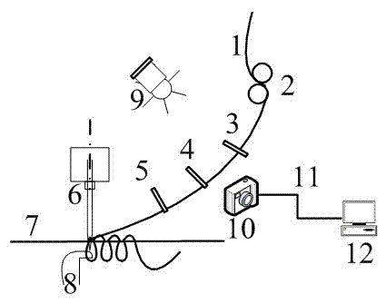
[0012] Such as figure 1 As shown, it is a schematic structural diagram of a non-contact yarn tension testing device. The non-contact yarn tension testing device includes a constant tension yarn guide roller 2, which is respectively arranged on the constant tension yarn guide roller 2 and the tufted carpet loom. On both sides of the yarn transmission path between the tufting needles 6, an angle-adjustable auxiliary light source 9 and a CCD image sensor 10, the CCD image sensor 10 is connected to a computer 12 through a USB interface data transmission device 11. A fixed yarn guide 3, a first adjustable yarn guide 4 and a second adjustable yarn guide are arranged on the yarn transmission path between the constant tension yarn guide roller 2 and the tufting needle 6 of the tufted carpet loom. Yarn device5.

[0013] During use, the yarn line segment image to be measured is continuously captured by the CCD image sensor 10, and after being enlarged and processed, it is input...


PUM


Abstract

The invention relates to a non-contact yarn tension testing device, which contains a constant tension thread guide roller, an auxiliary light source and a CCD image sensor. The invention is characterized in that the auxiliary light source and the CCD image sensor are respectively arranged at two sides of a yarn transport path between the constant tension thread guide roller and a tufting needle of a carpet tufting machine, and the CCD image sensor is connected to a computer through a USB interface data transmission device. The non-contact yarn tension testing device provided by the invention can be used to realize accurate detection of dynamic tension and raise carpet resolution, and is of great significance for dynamic tension measurement of yarn during operation.

Description

technical field [0001] The invention relates to a non-contact yarn tension test device using CCD technology, which is used for online detection and display of yarn tension in motion in textile, knitting, weaving and other industries, and belongs to the technical field of textile machinery. Background technique [0002] With the rapid development of my country's carpet industry, the demand for high-quality carpets and their types in the market has also increased significantly. In the tufted carpet weaving process, different pile heights can be obtained by changing the tension of the pile yarn during the looping process of the carpet by controlling the rotation speed of the rollers. Therefore, yarn tension is a very important parameter. The size and stability of tension are directly related to product quality and production efficiency. However, when the yarn bypasses the rollers and moves relative to various materials, frictional resistance will be generated, causing change...

Claims


Application Information

Patent Timeline
Patent Type & Authority Applications(China)
IPC IPC(8): D05C15/18G01L5/04
Inventor 徐洋孟婥孙以泽孙志军高晓平
Owner DONGHUA UNIV
Why Eureka
Try Eureka