Hydraulic system of loading machine working device

A technology for working devices and hydraulic systems, which is applied to earth movers/excavators, construction, etc., can solve problems such as excessive cost and large overflow loss, avoid high cost problems, reduce hydraulic system power loss, and improve The effect of power matching

Inactive Publication Date: 2012-06-27
SICHUAN UNIV
View PDF6 Cites 31 Cited by
  • Summary
  • Abstract
  • Description
  • Claims
  • Application Information

AI Technical Summary

Problems solved by technology

[0008] In order to solve the large overflow loss in the existing loader double-pump confluence system or double-pump confluence equivalent unloading system, further reduce the power loss of the hydraulic system of the loader work

Method used


Image

  • Hydraulic system of loading machine working device
  • Hydraulic system of loading machine working device
  • Hydraulic system of loading machine working device

Examples


Embodiment Construction

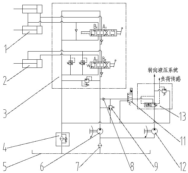
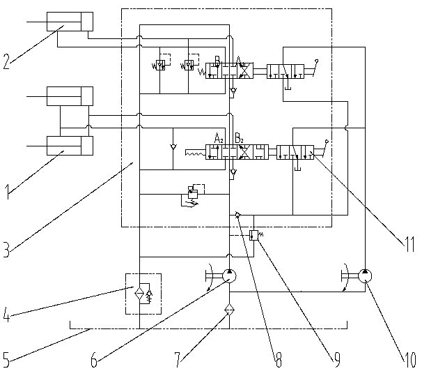
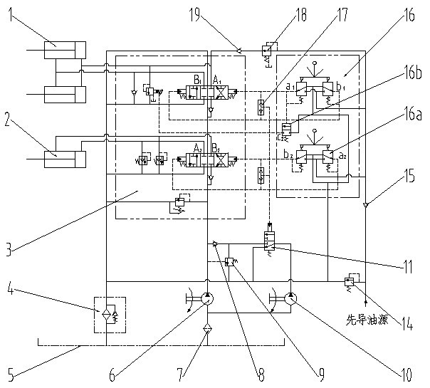
[0022] The hydraulic system principle of the loader working device of the present invention is as follows: figure 1 As shown, it consists of boom hydraulic cylinder 1, bucket hydraulic cylinder 2, multi-way reversing valve 3, oil filter 4 and 7, hydraulic oil tank 5, working pump 6, one-way valve 8, equivalent unloading valve 9, It consists of an auxiliary pump 10 and a confluence control valve 11. The working pump 6 and the auxiliary pump 10 form a dual-pump system to deliver hydraulic oil to the hydraulic system. The oil outlet of the working pump 6 is connected to the multi-way reversing valve 3, and A1 and B1 of the multi-way reversing valve 3 are respectively connected to the boom hydraulic cylinder. 1, A2 and B2 are respectively connected to the two chambers of the bucket hydraulic cylinder 2; the oil outlet of the auxiliary pump 10 is connected to the port of the confluence control valve 11P1, and the position of the spool of the confluence control valve 11 is related t...


PUM


Abstract

The invention discloses a hydraulic system of a loading machine working device, which belongs to the technical field of engineering machinery. Under different conditions, a handle is adopted to control whether an auxiliary pump and a working pump jointly supply oil for the working device in a flow converging mode, the problems that the hydraulic system of an existing working device is high in power loss and poor in matching of the pump and load, and simultaneously high cost of using two variable pumps is avoided. The hydraulic system of the loading machine working device comprises a movable arm hydraulic cylinder, a rotating bucket hydraulic cylinder, a multi-way reserving valve, an oil filter, an oil tank, the working pump, the auxiliary pump, an equivalent unloading valve and a flow converging control valve. The hydraulic system mainly used for a loading machine and can also be used for other engineering machinery.

Description

technical field [0001] The invention belongs to the technical field of construction machinery, and in particular relates to a hydraulic system of a loader working device. Background technique [0002] As we all know, the main operation methods of the reloader are shoveling operation and loading operation. In order to operate efficiently, the working device needs to frequently collect buckets, lift, unload, and lower. These actions are controlled and realized by the hydraulic system. [0003] The hydraulic system of the working device of the loader is composed of a working pump, a reversing multi-way valve, a hydraulic cylinder, pipelines and other accessories. The main reason for the energy loss of the hydraulic system of the loader working device is that the output flow and output pressure of the pump cannot match the flow and pressure required by the load, and there are more overflow losses, throttling losses and neutral unloading losses. [0004] In order to match the pu...

Claims


Application Information

Patent Timeline
IPC IPC(8): E02F9/22
Inventor 韩嘉骅袁成谭兆钧
Owner SICHUAN UNIV
Why Eureka
Try Eureka