A device for generating a plasma jet

A plasma and generating device technology, applied in the field of plasma, can solve the problems of high cost, limited plasma jet means, complex device structure, etc., and achieve the effects of low cost, simple structure, and optimized jet degree.

Active Publication Date: 2020-07-10
SHANGHAI UNIV OF ENG SCI
View PDF4 Cites 0 Cited by
  • Summary
  • Abstract
  • Description
  • Claims
  • Application Information

AI Technical Summary

Problems solved by technology

However, the conventional atmospheric pressure plasma jet generation device has complex structure, high cost and limited means of adjusting the plasma jet.

Method used


Image

  • A device for generating a plasma jet
  • A device for generating a plasma jet
  • A device for generating a plasma jet

Examples


Embodiment 1

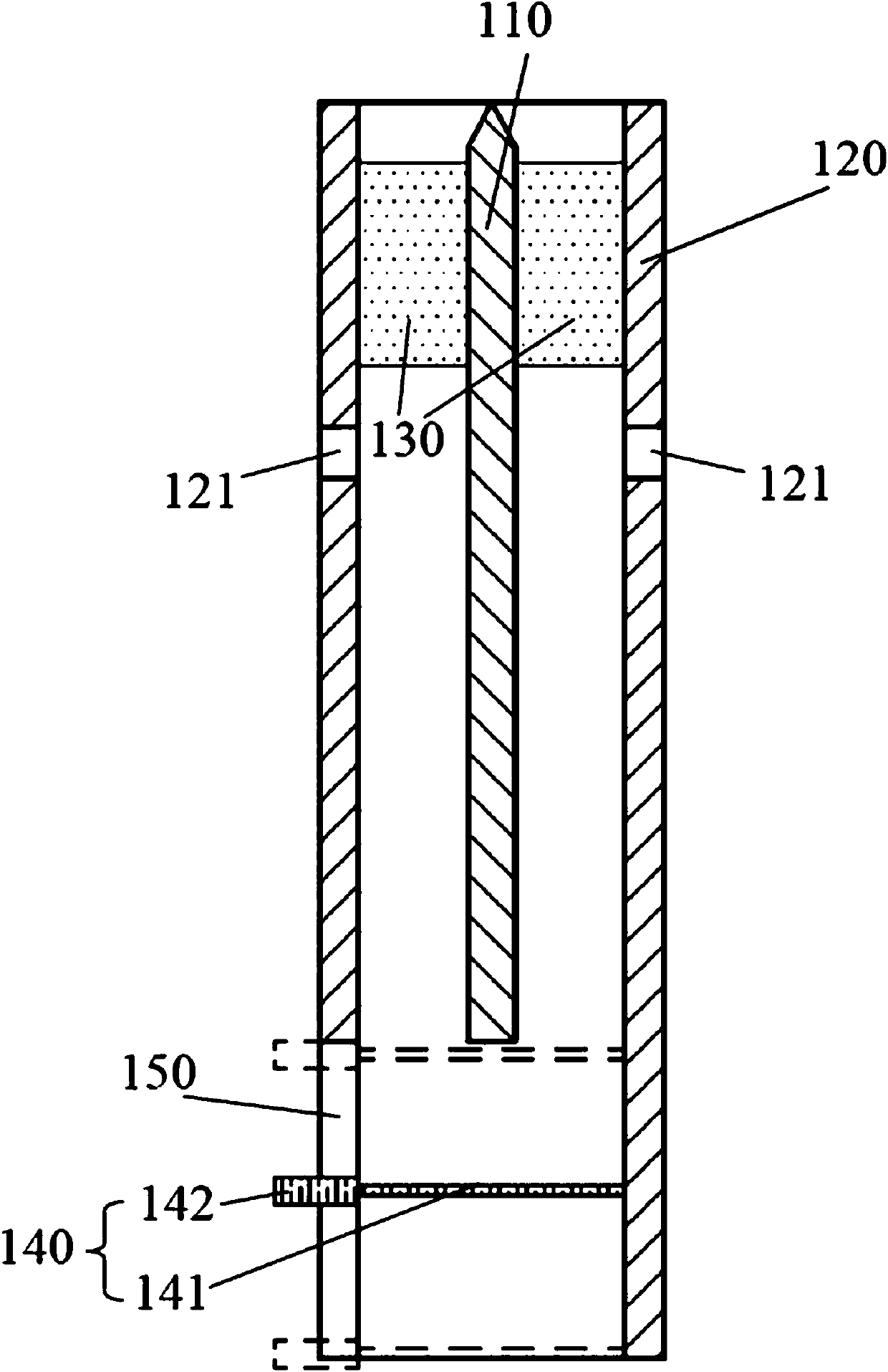
[0029] The present invention relates to a generating device of a plasma jet, such as figure 1 As shown, the device includes a waveguide assembly, a bottom shielding mechanism 140 and a void shielding mechanism 300 .

[0030] The waveguide assembly includes an inner conductor 110 and an outer conductor 120 , the inner conductor 110 and the outer conductor 120 are arranged coaxially and the inner conductor 110 is arranged inside the outer conductor 120 . The outer conductor 120 is cylindrical. The axial length of the outer conductor 120 is greater than that of the inner conductor 110, so that the lower end of the inner conductor 110 is surrounded by the outer conductor 120, and the coaxial structural characteristic dimensions of the outer conductor 120 and the inner conductor 110 will not cut off corresponding electromagnetic waves. The lower end of the outer conductor 120 is open. Upper ends of the inner conductor 110 and the outer conductor 120 are sealed by a sealing materi...


PUM


Abstract

The invention relates to a plasma jet generation device, which is coupled with a microwave power supply. The device includes a waveguide assembly and a bottom shielding mechanism arranged at the bottom of the waveguide assembly. The waveguide assembly includes an inner conductor and an outer conductor coaxially arranged , the inner conductor is arranged in the outer conductor, the upper side wall of the outer conductor is provided with an air inlet, and the lower side wall of the outer conductor is provided with a hole extending to the bottom of the outer conductor and penetrating in the radial direction The first slit, the bottom shielding mechanism moves vertically under the outer conductor through the first slit, and the bottom shielding mechanism is provided with a shield assembly capable of adjusting the shielding area. Compared with the prior art, the present invention has the advantages of simple structure, low cost, convenient adjustment and the like.

Description

technical field [0001] The invention relates to the field of plasma technology, in particular to a plasma jet generating device. Background technique [0002] Gas molecules are partially or fully ionized after gaining energy to achieve a plasma state. The gas in the plasma state is quasi-electrically neutral, that is, it has equal and opposite charges under the condition of macroscopic space-time scale. [0003] In traditional industrial applications, plasma is generally generated at low pressure. Typically, by adjusting the external electric field and magnetic field, the energy is preferentially transferred to electrons instead of heavy particles, and the transferred energy is transmitted to heavy particles through the collision of electrons to excite and ionize, thereby producing highly active substances. The low pressure increases the mean free path of the electrons and thus enables them to gain sufficient energy. In practice, an external excitation source is used, and...

Claims


Application Information

Patent Timeline
Patent Type & Authority Patents(China)
IPC IPC(8): H05H1/46
CPCH05H1/46H05H1/4622
Inventor 昌锡江朱珠王大伟梁逸轩方玲
Owner SHANGHAI UNIV OF ENG SCI
Why Eureka
Try Eureka