
Test device used for ultrasonic field shear force measurement

An experimental device and shear force technology, applied in the direction of measuring device, measuring fluid pressure, measuring fluid pressure through electromagnetic components, etc., can solve problems such as inability to deeply understand the mechanism of ultrasonic action, inability to optimize ultrasonic power matching, etc., and achieve good fixation effect , Simple structure, optimized power matching effect

Inactive Publication Date: 2014-12-03
JIANGSU UNIV
View PDF6 Cites 0 Cited by
  • Summary
  • Abstract
  • Description
  • Claims
  • Application Information

AI Technical Summary

Problems solved by technology

[0004] The purpose of the present invention is to overcome the defects in the prior art that the mechanism of action of the ultrasonic wave and the power matching of the ultrasonic wave cannot be optimized due to the absence of an experimental device for real-time transmission of the shear force distribution structure of the entire ultrasonic field, thereby proposing a method for using The experimental device for measuring the shear force in the ultrasonic field can measure the shear force in the entire ultrasonic field in real time

Method used


Image

  • Test device used for ultrasonic field shear force measurement
  • Test device used for ultrasonic field shear force measurement
  • Test device used for ultrasonic field shear force measurement

Examples


Embodiment Construction

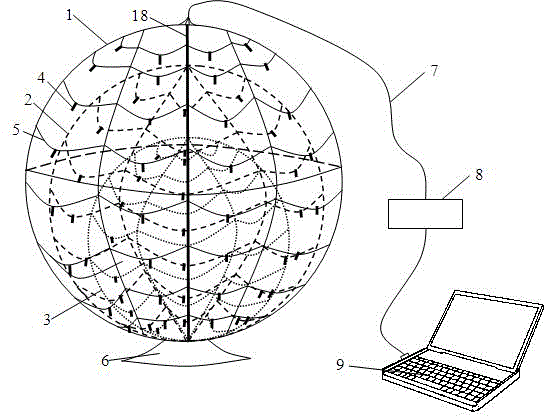
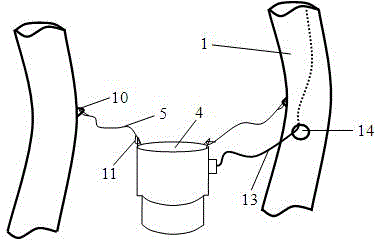
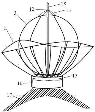
[0025] see figure 1 , is a schematic diagram of the overall structure of an experimental device for ultrasonic field shear force measurement according to the present invention. A three-level spherical sensor array body structure composed of frame 3. The diameters of the first, second and third spherical steel frames 1, 2, and 3 are sequentially set together in order from large to small. The second spherical steel frames 2 are set on the inner bottom of the first spherical steel frame 1, and the third The first-level spherical steel frame 3 is set on the inner bottom of the second-level spherical steel frame 2. During the suit, the third-level spherical steel frame is closely attached to the center bottom of the vertical center line. The diameter of the three-stage spherical steel frame can be reasonably determined according to the size of the reaction vessel. For example, for a container with a length and width of 50 cm, the diameters of the first, second, and third-stage sph...


PUM


Abstract

The invention discloses a test device used for ultrasonic field shear force measurement. The test device is used for measuring the shear force generated by propagation of ultrasonic waves in liquid and comprises a three-level spherical sensor array body structure which is formed by a first-level sphere steel frame, a second-level sphere steel frame and a third-level sphere steel frame, wherein the first-level sphere steel frame, the second-level sphere steel frame and the third-level sphere steel frame are sequentially installed together in a sleeved mode from the large size to the small size Bottoms of centers of the first-level sphere steel frame, the second-level sphere steel frame and the third-level sphere steel frame are tightly attached. The sphere steel frame of each level is formed by even construction of a plurality of blank pipe supports at intervals along the circumference direction, wherein the plurality of blank pipe supports have a common perpendicular center line, sections of the blank pipe supports are round and diameters of the blank pipe supports are identical. A plurality of elastic fixing ropes are connected between each two adjacent blank pipe supports in the sphere steel frame of each level, and the plurality of elastic fixing ropes are distributed at intervals from the bottom to the top of the sphere steel frame of each level. A micro pressure sensor is arranged on each elastic fixing rope. By utilization of the three-level spherical sensor array body structure, the distribution condition of shear force in the whole ultrasonic field is reflected, and by the elastic connection mode, the shear force generated in the liquid influenced by the ultrasonic field is measured.

Description

technical field [0001] The invention relates to an experimental device for measuring shear force in an ultrasonic field, which measures the shear force generated by ultrasonic waves propagating in liquid. Background technique [0002] The use of power ultrasonic waves to propagate in liquids can generate huge shear forces, for example, when the sound wave pressure reaches 100kPa, the power density reaches 0.35W / cm 2 , the magnitude of the shear force can split the liquid molecules into cavities (cavitation nuclei), and when the ultrasonic pressure reaches the maximum in one and a half weeks, it is crushed due to the increase of the surrounding pressure. At this time, the liquid molecules collide violently. A very large secondary shear force is generated. The strong shear force generated by the ultrasonic field can be used to separate the adsorbed substances. Using this principle, the ultrasonic generator can be used to make ultrasonic cleaners, ultrasonic cell pulverizers, ...

Claims


Application Information

Patent Timeline
Patent Type & Authority Patents(China)
IPC IPC(8): G01L9/00
Inventor 张荣标杨宁徐佩锋张磊
Owner JIANGSU UNIV
Learn More