Eureka AIR delivers breakthrough ideas for toughest innovation challenges, trusted by R&D personnel around the world.

Apparatus for realizing automatic channel switching control of large dam monitoring apparatus collective line box and method thereof

A technology of monitoring instruments and junction boxes, which is applied in the field of devices for realizing passive automatic channel switching control of junction boxes of dam monitoring instruments. Toggle control, reduce the effect of using the total amount of length

Active Publication Date: 2012-06-27
CHINA GEOKON INSTR
View PDF2 Cites 3 Cited by
  • Summary
  • Abstract
  • Description
  • Claims
  • Application Information

AI Technical Summary

Problems solved by technology

[0003] The present invention is aimed at the requirement of manual near-ground control for the dam monitoring instrument junction box currently used and the automation product requirements of the existing dam monitoring instrument junction box To solve the problem of power supply but no power source can be found at the geotechnical engineering site, a device for realizing the automatic channel switching control of the junction box of the dam monitoring instrument is provided, which can make the junction box of the dam monitoring instrument realize passive work and automatic channel switch control

Method used


Image

  • Apparatus for realizing automatic channel switching control of large dam monitoring apparatus collective line box and method thereof
  • Apparatus for realizing automatic channel switching control of large dam monitoring apparatus collective line box and method thereof
  • Apparatus for realizing automatic channel switching control of large dam monitoring apparatus collective line box and method thereof

Examples


Embodiment Construction

[0025] The present invention will be described below in conjunction with the drawings.

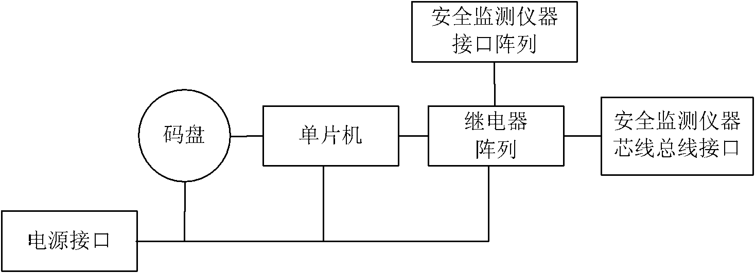
[0026] The invention discloses a device for realizing automatic channel switching control of a dam monitoring instrument junction box. The device includes an automatic dam monitoring instrument junction box, a junction box controller and a communication cable.

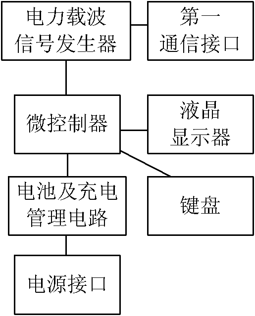
[0027] The optimal structure of the junction box controller is as follows figure 2 As shown, the hub controller includes a microcontroller, a battery and charging management circuit, a power interface, a keyboard, a liquid crystal display, a power carrier signal generator and a first communication interface. Among them, the power carrier signal generator and the microcontroller are connected to each other, the power carrier signal generator is connected to the first communication interface, the microcontroller is connected to the liquid crystal display and the keyboard, and the battery and charging management circuit are respectively co...


PUM


Abstract

The invention relates to an apparatus for realizing automatic channel switching control of a large dam monitoring apparatus collective line box and a method thereof. The apparatus comprises the large dam monitoring apparatus collective line box, a collective line box controller and a communication cable. The collective line box controller comprises a power carrier wave signal generator and a microcontroller which are mutually connected. The power carrier wave signal generator is connected with a first communication interface. The microcontroller is connected with a display device, an operation instruction input device and a power supply interface. The large dam monitoring apparatus collective line box comprises a second communication interface, a power carrier wave decoding circuit, a channel selection control circuit and a relay array which are connected in order. The relay array is provided with a safety monitoring apparatus interface array and a safety monitoring apparatus core wire bus interface. The apparatus also comprises a power taking circuit. The communication cable is connected with the first communication interface and the second communication interface. According to the apparatus and the method, the large dam monitoring apparatus collective line box realizes passivity work and automatic channel switching control, and the apparatus and the method have very practical meaning to realization of large dam safety monitoring in a construction period.

Description

Technical field [0001] The invention relates to the technical field of safety monitoring of dams and geotechnical engineering, in particular to a device and method for realizing passive automatic channel switching control of a dam monitoring instrument junction box. Background technique [0002] In the field of safety monitoring technology for dams and geotechnical engineering, the dam monitoring instrument junction box is an indispensable important equipment, especially during the construction period. Considering various factors such as structural strength, waterproofing and sealing, power supply difficulties, etc., the manual control of the junction box is basically adopted, which not only increases the labor intensity, but also requires manual operation near the ground. This is for dangerous areas (such as high Slope) is an inconvenient task. Although there are already some dam monitoring instrument junction box automation products, they all need regular power supply, such as...

Claims


Application Information

Patent Timeline
IPC IPC(8): G05B19/418H04B3/54
CPCY02P90/02
Inventor 毛良明沈省三江修
Owner CHINA GEOKON INSTR
Why Eureka
Eureka Blog
Learn More