Scene non-uniform correction method for scanning type infrared imaging system

An infrared imaging system and non-uniform correction technology, which is applied to the components of TV systems, image enhancement, image communication, etc., can solve problems such as poor image quality, slow convergence speed, and failure to consider the noise characteristics of scanning infrared imaging systems.

Inactive Publication Date: 2012-06-27
HUAZHONG UNIV OF SCI & TECH
View PDF3 Cites 16 Cited by
  • Summary
  • Abstract
  • Description
  • Claims
  • Application Information

AI Technical Summary

Problems solved by technology

Directly applying the scene non-uniformity correction method of the staring infrared imaging system to the scanning infrared imaging system has certain defects: it leads to

Method used


Image

  • Scene non-uniform correction method for scanning type infrared imaging system
  • Scene non-uniform correction method for scanning type infrared imaging system
  • Scene non-uniform correction method for scanning type infrared imaging system

Examples


Embodiment Construction

[0030] The present invention will be further described below in conjunction with the accompanying drawings and embodiments.

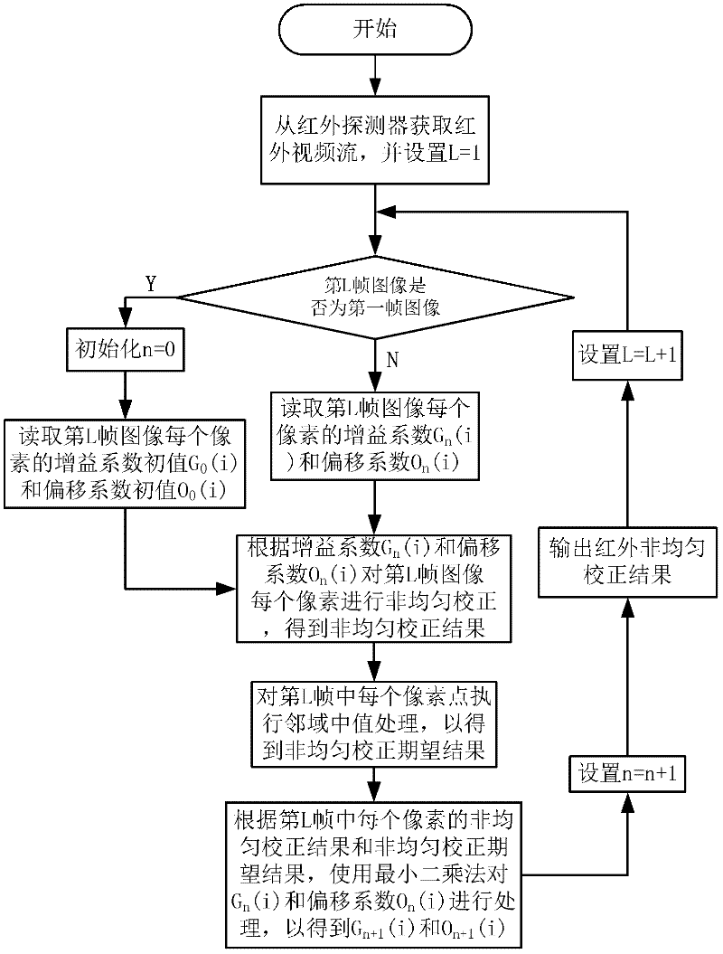
[0031] Such as figure 1 As shown, the scene non-uniform correction method of the scanning infrared imaging system of the present invention includes the following steps:

[0032] (1) Obtain the high temperature T respectively H and low temperature T L The uniform radiation scene image under x i`j` (T H ) and x i`j` (T L ), where i` is the column coordinate of the pixel of the uniform radiation scene image, and j` is the row coordinate of the pixel;

[0033] (2) Calculate the gray mean value of the uniform radiation scene image line by line along the scanning direction to obtain the i-th pixel in the line scanning detector at high temperature T H The average grayscale response under X i (T H ) and low temperature T L The average grayscale response under X i(T L ),Calculated as follows: X i ...


PUM


Abstract

A scene non-uniform correction method for a scanning type infrared imaging system comprises the following steps that: an infrared video stream is obtained from an infrared detector, an L is set to be 1, the L(th) frame image of the infrared video stream is judged whether to be the first frame of the infrared video stream, if the L(th) frame image is the first frame of the infrared video stream, an n is set to be 0, the grain coefficient Gn (i) and offset coefficient On (i) of each pixel of a linear detector are read, non-uniform correction is carried out on each pixel in the L(th) frame image according to the grain coefficient Gn (i) and the offset coefficient On (i) so as to obtain non-uniform correction results, neighbor median processing is performed on the non-uniform correction result of each pixel in the L(th) frame image so as to obtain non-uniform correction expectation results, the least square method is adopted to process the grain coefficient Gn (i) and the offset coefficient On (i) according to the non-uniform correction results and the non-uniform correction expectation results, so that Gn+1 (i) and On+1 (i) are obtained. By adopting the scene non-uniform correction method, the ghost phenomenon is not obvious, the image quality is better and the method has a good application prospect.

Description

Technical field: [0001] The invention relates to a method for correcting scene non-uniformity of an infrared image, more specifically, the invention relates to a method for correcting scene non-uniformity of a scanning infrared imaging system. Background technique [0002] The infrared imaging system has strong anti-interference ability, good concealment performance, strong atmospheric penetration ability, and is suitable for many special occasions. At present, the widely used infrared imaging systems are divided into two categories: one is the staring infrared imaging system, the optical part of the system focuses the infrared scene on the infrared focal plane; the other is the scanning infrared imaging system, the system is scanned by the optical machine The two parts of the infrared focal plane and the line array are enough, and the system gradually maps the scene to the infrared imaging line array along the scanning direction. [0003] Whether it is in the scanning infr...

Claims


Application Information

Patent Timeline
IPC IPC(8): G06T5/00H04N5/21
Inventor 樊凡马泳周波梁琨
Owner HUAZHONG UNIV OF SCI & TECH
Why Eureka
Try Eureka