Vertical structure of lead screw front-loading machine tool

A lead screw and machine tool technology, applied in the field of vertical machine tool structure in front of the lead screw, can solve the problem of affecting the accuracy of the machine tool, difficult to overcome the deformation of the vertical structure of the machine tool, lack of vertical closed hydrostatic guideway gap adjustment device and method, etc. problems, to achieve the effect of simple vertical structure, reduced warpage, easy manufacture and installation

Inactive Publication Date: 2013-08-21
XIAMEN UNIV
View PDF15 Cites 0 Cited by
  • Summary
  • Abstract
  • Description
  • Claims
  • Application Information

AI Technical Summary

Problems solved by technology

In Chinese patents 201020571582, 200620045212, 200620166169 and 200810071351.6, the structures of four hydrostatic guide rails are disclosed respectively. In Chinese patent 200710070272, a straightness adjustment method of a hydrostatic guide rail is disclosed. Although they have their own characteristics, There is still a lack of devices and methods for adjusting the clearance of vertical closed static pressure guide rails, and it is difficult to overcome the problem of vertical structural deformation of machine tools, which affects the accuracy of machine tools

Method used


Image

  • Vertical structure of lead screw front-loading machine tool
  • Vertical structure of lead screw front-loading machine tool
  • Vertical structure of lead screw front-loading machine tool

Examples


Embodiment Construction

[0016] The present invention will be further described below in conjunction with drawings and embodiments.

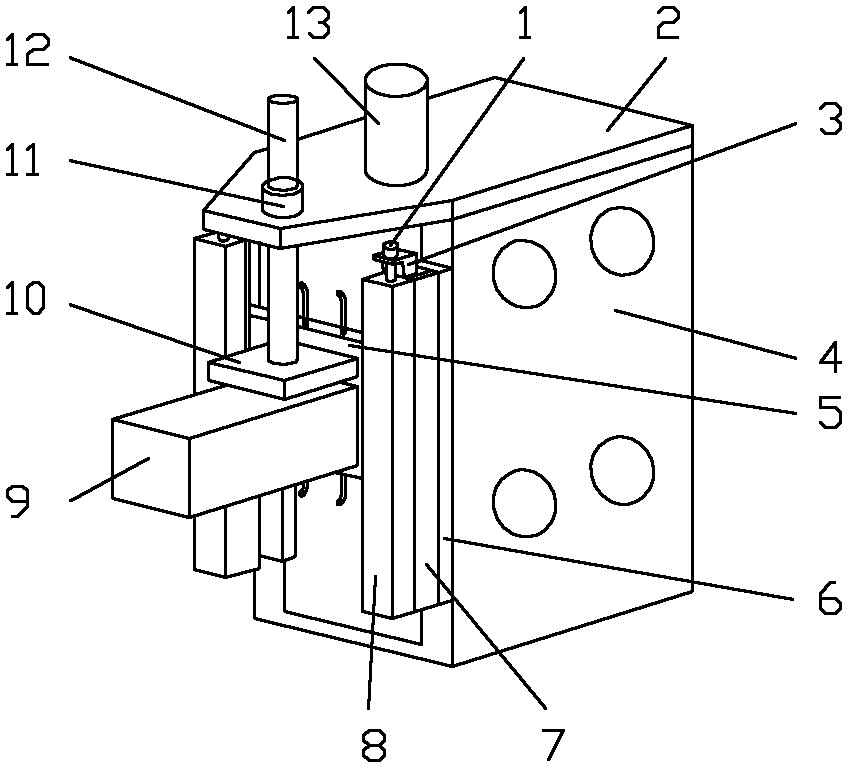
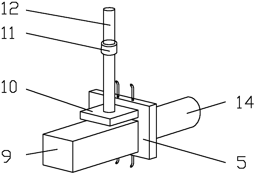
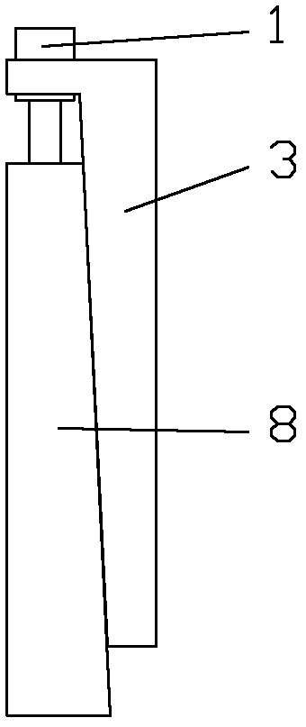
[0017] see Figure 1~4 , the embodiment of the present invention is provided with column 4, top plate 2, vertical motor 13, fixed guide rail 6, moving guide rail 5, main shaft box 9, main shaft motor 14, lead screw 12, lead screw lower nut 10, lead screw upper nut seat 11 and 2 sets of wedge assemblies.

[0018] The top plate 2 is fixed on the upper end of the column 4, the vertical motor 13 is fixed on the top plate 2, the fixed guide rail 6 is provided with 2 rails, and the 2 rails are fixed on the left and right sides of the column 4 and arranged symmetrically, and the moving guide rail 5 is flat. The guide rail, the movable guide rail 5 and the fixed guide rail 6 are slidably matched, the spindle box 9 is fixed on the front of the movable guide rail 5, the spindle motor 14 is fixed on the reverse side of the movable guide rail 5, the lead screw 12 is located in fro...


PUM


Abstract

The invention relates to a vertical structure of a lead screw front-loading machine tool, and relates to the vertical structure of the machine tool. The vertical structure is provided with a upright post, a top plate, a vertical motor, a fixed slide guide, a moving slide guide, a main shaft box, a main shaft motor, a lead screw, a lower nut of the lead screw, an upper nut base of the lead screw and two groups of contracting strip assemblies, wherein the top plate is fixed on the upper end of the upright post, the vertical motor is fixed on the top plate, and the fixed slide guide is provided with two rail bars; the two rail bars are fixed on the two sides of the upright post, the moving slide guide is matched with the fixed slide guide, and the main shaft box and the main shaft motor are respectively fixed on the positive and negative surfaces of the moving slide guide; the lead screw is positioned in front of the frontage of the upright post, the upper end of the lead screw is connected with the top plate, and the lower end of the lead screw is connected with the front of the moving slide guide; each group of contracting strip assemblies is provided with a contracting strip, a contracting strip press plate and a contracting strip adjustment bolt, and each contracting strip press plate is positioned in front of the frontage of the moving slide guide; each contracting strip press plate is connected with the rail bars of the fixed slide guide, each contracting strip press plate is positioned in the front of the frontage of the moving slide guide and is pressed tightly on the contract strips, and each contracting strip adjustment bolt is arranged on the top of each contracting strip; and the lower end of each contracting strip adjustment bolt is fixedly connected with each contracting strip press plate, and the upper end of each contracting strip adjustment bolt passes through the top of each contracting strip.

Description

technical field [0001] The invention relates to a vertical structure of a machine tool, in particular to a vertical machine tool structure with a leading screw. Background technique [0002] Hydrostatic support technology is widely used in precision machine tools due to its advantages of good rigidity, impact resistance, wear resistance and good accuracy retention. At present, the hydrostatic support technology is widely used in the guide rail devices in the horizontal direction of precision machine tools, especially closed hydrostatic guide rails. However, there are few machine tools that use hydrostatic support technology on the vertical structure of the machine tool, mainly because the vertical hydrostatic fluid cannot provide complete rigid support when the vertical structure layout and the operation of the hydrostatic support device are not ideal. , so that the entire vertical drive and transmission structure forms a cantilever beam that rotates around the fulcrum of t...

Claims


Application Information

Patent Timeline
Patent Type & Authority Patents(China)
IPC IPC(8): B23Q1/01B23Q5/40B23Q1/26
Inventor 彭云峰郭隐彪王振忠林建华姜涛林晓辉
Owner XIAMEN UNIV
Why Eureka
Try Eureka