
Two-stage shuttle-type reducing crushing device

A crushing device and shuttle-type technology, applied in the field of processing machinery, can solve problems such as inability to save energy, drive power, incomplete crushing, and long crushing time, and achieve the effects of complete and efficient processing, simple vertical structure, and reasonable structural design

Inactive Publication Date: 2018-09-18
SUZHOU RUISHUO ENVIRONMENT TECH CO LTD
View PDF9 Cites 1 Cited by
  • Summary
  • Abstract
  • Description
  • Claims
  • Application Information

AI Technical Summary

Problems solved by technology

[0003] In order to solve the above problems, the present invention is proposed, which overcomes the problems of the currently used crushing device, such as the use of the straight-column crushing roller crushing structure, which causes the crushing operation area to be narrow during the crushing process, resulting in long crushing time and incomplete crushing, etc., and solves the problem The currently used crushing device requires multiple operations for crushing the guide material, which is time-consuming and laborious, and the power drive structure is single, and the drive power cannot be selected for energy saving, resulting in energy waste and other problems. This makes the present invention have reasonable structural design, simple vertical structure, and The process is complete and efficient, the crushing is fast, the quality is high, the advantages of economy and environmental protection, etc.

Method used


Image

  • Two-stage shuttle-type reducing crushing device
  • Two-stage shuttle-type reducing crushing device
  • Two-stage shuttle-type reducing crushing device

Examples


Embodiment Construction

[0017] The following will clearly and completely describe the technical solutions in the embodiments of the present invention with reference to the accompanying drawings in the embodiments of the present invention. Obviously, the described embodiments are only some, not all, embodiments of the present invention. Based on the embodiments of the present invention, all other embodiments obtained by persons of ordinary skill in the art without making creative efforts belong to the protection scope of the present invention.

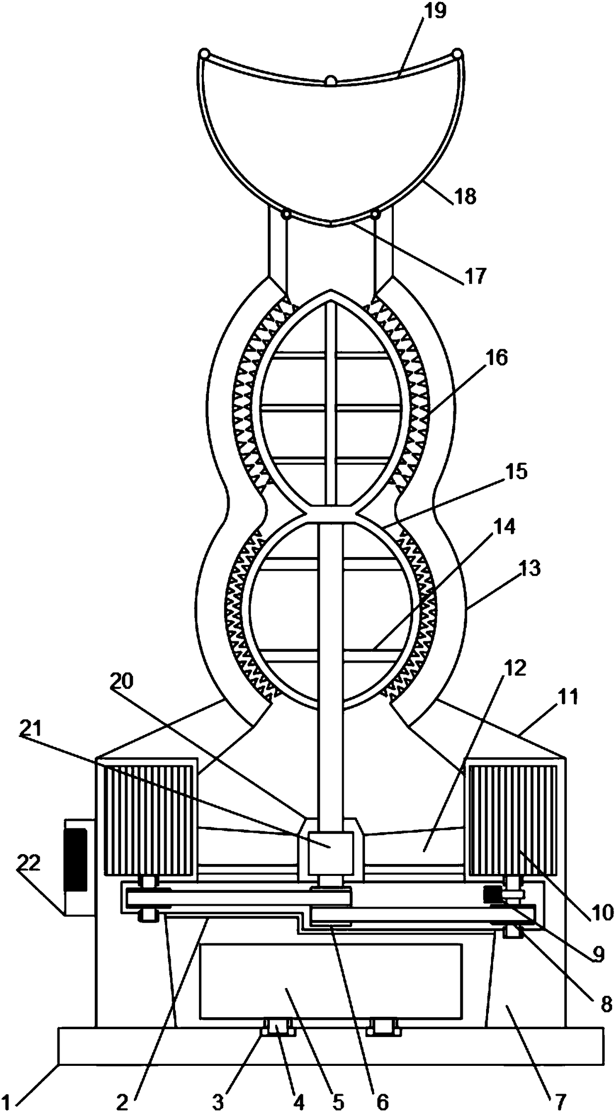
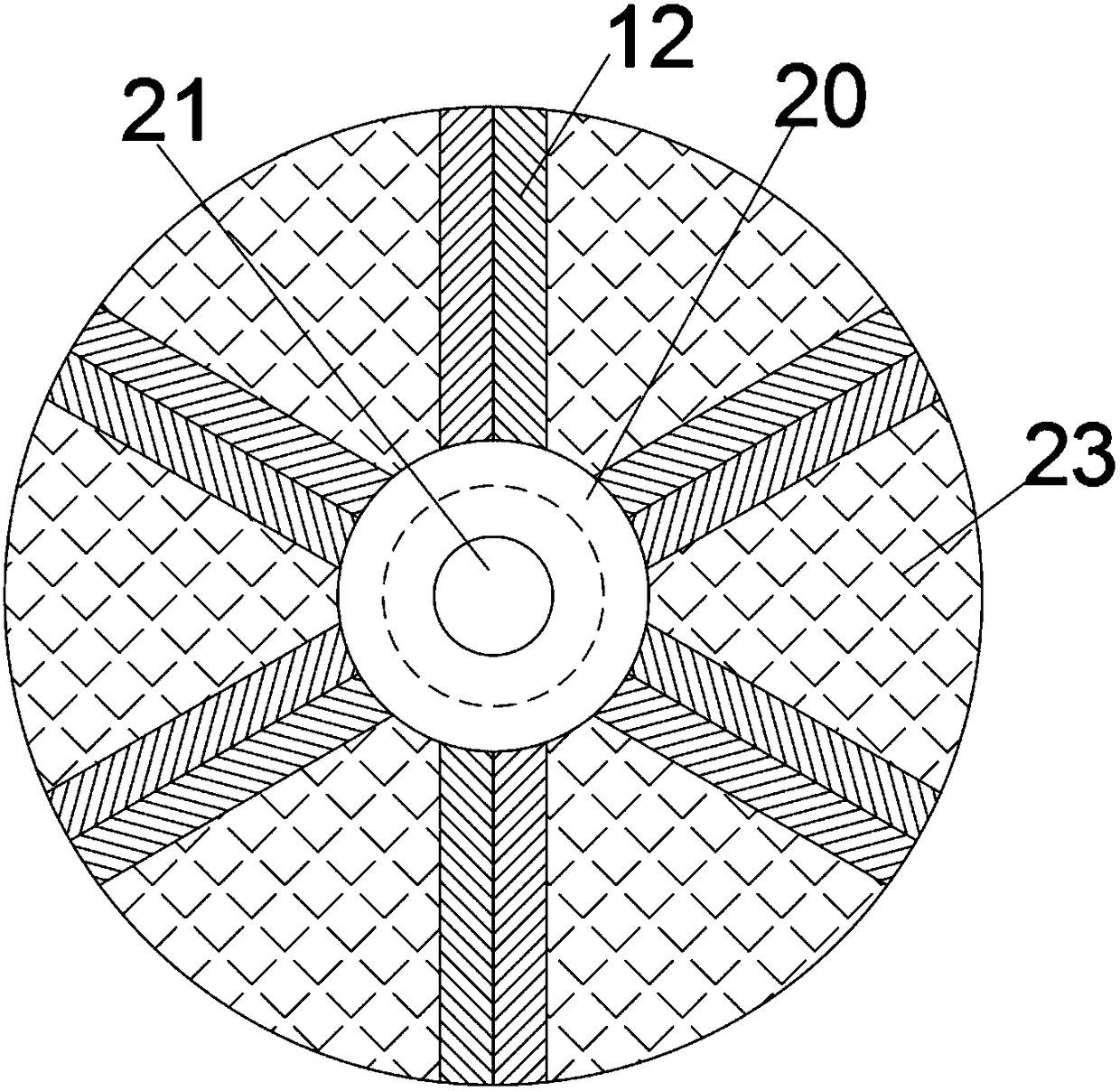
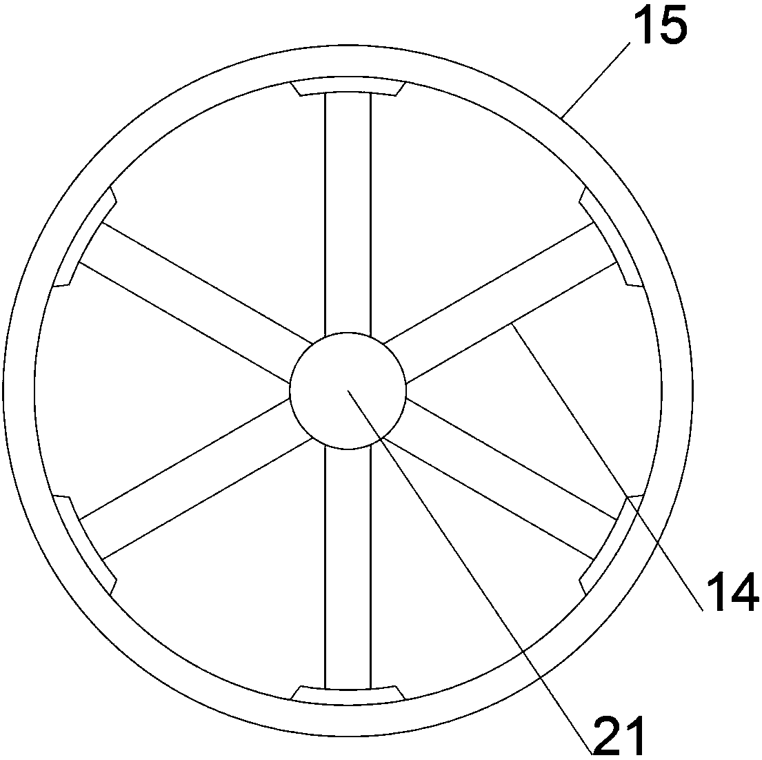
[0018] see Figure 1~3 , in an embodiment of the present invention, a two-stage shuttle-type variable-diameter crushing device includes a horizontally arranged fixed mounting plate 1, and a collecting car 5 is arranged at the middle position of the upper end of the fixed mounting plate 1 in conjunction with the blanking hole, and the collecting material The lower order of the car 5 is provided with guide rollers 4 symmetrically, and the upper end of the fixed ...


PUM


Abstract

The invention discloses a two-stage shuttle-type reducing crushing device. The two-stage shuttle-type reducing crushing device comprises a horizontal fixing mounting board; a supporting mounting tubeis vertically and upwards arranged in the middle of the upper end of the fixing mounting board; combined drive structures are arranged on the upper half section of the supporting mounting tube in a bilateral symmetry mode and comprise drive motors symmetrically and vertically embedded in the upper half section of the supporting mounting tube; transmission mounting cavities are arranged at the positions, at the lower ends of the drive motors, of the supporting mounting tube in a matched mode; a transmission mounting cover is horizontally arranged between the transmission mounting cavities in the left and right sides; a double-layer drive belt wheel is vertically arranged in the middle of the interior of the transmission mounting cover; the upper end of the double-layer drive belt wheel vertically and upwards extends to be provided with a limiting transmission shaft; and a two-stage reducing shuttle-type crushing tube is arranged at the upper end of the limiting transmission shaft and matched with a two-stage shuttle-type crushing mounting tube. The two-stage shuttle-type reducing crushing device has the advantages of being reasonable in structural design, simple in vertical structure, complete and efficient in machining process, rapid in crushing, high in quality, economical, environmentally friendly and the like.

Description

technical field [0001] The invention relates to the field of processing machinery, in particular to a two-stage shuttle type variable-diameter crushing device. Background technique [0002] The crushing of solid waste refers to the process of using external force to overcome the cohesive force between solid waste material points to split large pieces of solid waste into small pieces of solid waste. Crushing is one of the technologies for solid waste pretreatment. Through crushing, the size and shape of solids are controlled. , which is beneficial to the recycling and reduction of solid waste. Due to the imperfect design of traditional crushing devices, various problems have appeared in actual use. [0003] In order to solve the above problems, the present invention is proposed, which overcomes the problems of the currently used crushing device, such as the use of the straight column type crushing roller crushing structure, which causes the crushing operation area to be narro...

Claims


Application Information

Patent Timeline
Patent Type & Authority Applications(China)
IPC IPC(8): B02C19/00B02C23/02
CPCB02C19/00B02C23/02B02C2201/06
Inventor 张培磊
Owner SUZHOU RUISHUO ENVIRONMENT TECH CO LTD
Learn More