Fingerprint identification stamp

A technology of fingerprint identification and seal, which is applied in the field of seals, can solve problems such as the complex structure of fingerprint identification seals, and achieve the effect of ensuring use authority and safe use, and simple structure

Inactive Publication Date: 2012-07-04
张月婵
View PDF6 Cites 2 Cited by
  • Summary
  • Abstract
  • Description
  • Claims
  • Application Information

AI Technical Summary

Problems solved by technology

[0003] In the prior art, the structure of the fingerprint recognition seal is very complicated

Method used


Image

  • Fingerprint identification stamp
  • Fingerprint identification stamp
  • Fingerprint identification stamp

Examples


Embodiment Construction

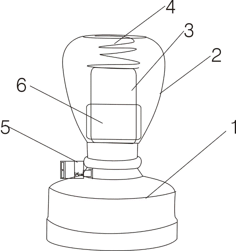
[0015] See Figure 1-5 , a fingerprint identification stamp, comprising a housing 1, a handshake part 2, and a main stamp core 3, the upper part of the stamp main core 3 is installed with a first spring 4 connected to the handshake part 2, and the lower part of the stamp main core 3 is movably installed in the shell 1, on the side of the shell 1, a control unit 5 that presses down the main stamp core 3 is fixed, and a fingerprint identification chip 6 is set in the handshake unit 2, and the fingerprint identification chip 6 is connected to the control unit 5 through a wire 13.

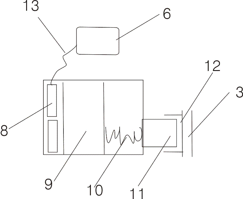
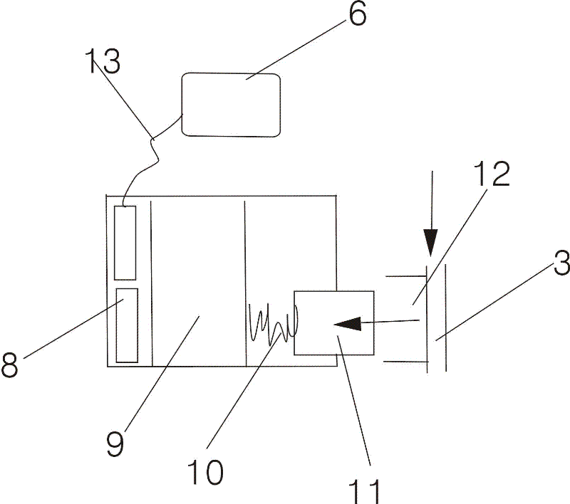
[0016] Described control part 5 comprises casing 1 and the battery 8 in casing, the iron core 9 that is wound with coil, the second spring 10, iron piece 11; , iron piece; the front end of the iron piece 11 is the bayonet socket 12 of the main core 3 of the seal.

[0017] The fingerprint identification chip is connected to the control unit through wires, and the battery power line is connected to the ...


PUM


Abstract

The invention relates to a fingerprint identification stamp, which comprises a shell, a handhold part and a stamp main core, wherein the upper part of the stamp main core is provided with a first spring which is connected in the handhold part; the lower part of the stamp main core is movably arranged in the shell; a control part for pressing down the stamp main core is fixed on the side of the shell; a fingerprint identification chip is arranged in the handhold part and is connected with the control part through a wire; the control part comprises a shell, and a battery, an iron core wound with a coil, a second spring and an iron member in the shell; the battery, the iron core wound with the coil, the second spring and the iron member are arranged from outside to inside in sequence; and the front end of the iron member is a clamping port for the stamp main core. The fingerprint identification stamp has a simple structure; and the right of using of the stamp is guaranteed.

Description

technical field [0001] The invention relates to a stamp, in particular to a fingerprint identification stamp. Background technique [0002] Chinese Patent Application No. 201010583112.6 titled "Fingerprint Recognition Seal" discloses: a fingerprint recognition seal, including a stamp housing with a chute cavity; a seal surface arranged at the front end of the chute cavity; A spring is installed between the bottom of the chute cavity, so that the sliding frame partially protrudes from the chute cavity under normal conditions, and can be retracted into the chute cavity after being pressed, so that the printed surface protrudes from the front of the housing; And the fingerprint sensor arranged on the housing; the control module connected to the fingerprint sensor; the motor arranged on the sliding frame and connected to the control module; the power supply connected to the control module and the motor; wherein the motor transmission is connected to a transmission lock arranged ...

Claims


Application Information

Patent Timeline
IPC IPC(8): B41K1/02B41K1/56G06K9/00
Inventor 张月婵
Owner 张月婵
Why Eureka
Try Eureka