Buffering protection type oil gas suspension system and vehicle

An oil-air suspension and protection technology, which is applied to vehicle components, suspensions, elastic suspensions, etc., can solve the problems of oil-air suspension system damage, reduce vehicle height, and small structural size, and achieve easy oil circuit transformation and ensure safety and reliability, the effect of simple structure

Active Publication Date: 2014-06-18
ZOOMLION HEAVY IND CO LTD
View PDF4 Cites 0 Cited by
  • Summary
  • Abstract
  • Description
  • Claims
  • Application Information

AI Technical Summary

Problems solved by technology

[0004] The development of vehicles, especially heavy-duty vehicles, makes their volume increasingly large, while road driving standards restrict the total weight, total size, and axle load of vehicles, thus putting forward higher requirements for oil-pneumatic suspension systems. Therefore, the oil-air suspension system should meet its vibration damping performance and its own structural size should be as small as possible, so as to reduce the height of the vehicle and make the vehicle have better road performance, but shortening the stroke of the oil-air suspension will inevitably make the vehicle meet the requirements of large Risk of rigid collisions during stroke damping
[0005] Specifically, there is a height limit requirement in the process of vehicle driving on the road, and the stretching and compression strokes of the oil-air suspension of large-scale engineering vehicles are about 140mm respectively. The stroke of the suspension cylinder of the oil-air suspension system directly affects the height of the vehicle. The existing oil-air suspension system Usually, shortening the compression stroke of the suspension oil cylinder in the oil-air suspension system in order to reduce the height of the vehicle may cause rigid collision between the piston rod of the suspension oil cylinder and the bottom of the cylinder barrel, as well as the frame and the suspension oil cylinder, which will cause damage to the oil-air suspension system

Method used


Image

  • Buffering protection type oil gas suspension system and vehicle
  • Buffering protection type oil gas suspension system and vehicle

Examples


Embodiment approach

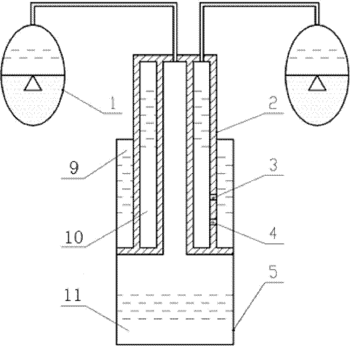
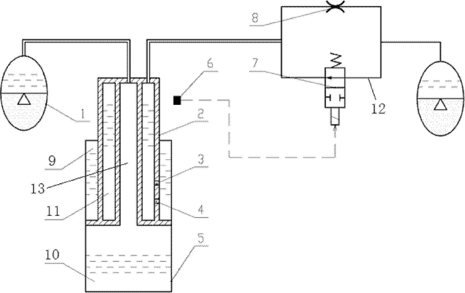
[0040] For example, specifically, the above-mentioned reversing valve adopts an electronically controlled reversing valve, and the buffer protection type oil-gas suspension system of the present invention further includes a travel switch 6. Preferably, the travel switch 6 is a proximity switch (ie a non-contact travel switch) The travel switch 6 is connected to the circuit of the reversing valve and is arranged at a predetermined position of the piston rod of the suspension cylinder, for example, on the rod head of the piston rod. In the case where the travel switch 6 adopts the proximity switch, the setting position of the proximity switch can be various, and is not limited to being installed on the piston rod. For example, it is installed on the cylinder or installed near the suspension cylinder through a bracket. It is enough to detect the position of the piston rod relative to the cylinder. In the case where the travel switch 6 of the present invention is the proximity swit...


PUM


Abstract

A buffering protection type oil gas suspension system comprises a suspension oil cylinder and energy accumulators (1) on two sides. One of the energy accumulators (1) on the two sides is communicated with a rodless cavity of the suspension oil cylinder, the other energy accumulator is communicated with a rod cavity of the suspension oil cylinder, a throttle orifice (8) is parallelly connected with a buffering oil channel (12), a selector valve is arranged on the buffering oil channel (12), and the buffering oil channel (12) is cut off when a compression stroke of the suspension oil cylinder reaches a preset compression stroke. In addition, the invention provides a vehicle comprising the buffering protection type oil gas suspension system. The buffering oil channel among the rod cavity of the suspension oil cylinder and the accumulators is cut off when the compression stroke of the suspension oil cylinder reaches the preset compression stroke, accordingly, hydraulic oil in the accumulators only can flow into the rod cavity of the suspension oil cylinder via the throttle orifice, oil inlet quantity of the rod cavity is reduced remarkably, a compression damping effect is quickly strengthened, and an effective buffering protection effect is realized.

Description

Technical field [0001] The invention relates to an oil and gas suspension system, in particular to a cushion protection type oil and gas suspension system with a cushion protection function. In addition, the present invention also relates to a vehicle with the cushion protection type hydro-pneumatic suspension system. Background technique [0002] Suspension technology is one of the key technologies that determine the ride comfort of automobiles. Over the past 100 years of automobile development, various suspension forms such as metal springs, air springs, oil-air springs, rubber springs, and liquid springs have been formed. Its unique advantages are widely used in heavy vehicles. [0003] figure 1 A schematic diagram showing the principle of an oil-air suspension system in the prior art. First, the volume of the rodless cavity 9 is enlarged during compression, and the oil in the piston cavity 10 flows into the rodless cavity 9 through the orifice 3 and the check valve 4 at this t...

Claims


Application Information

Patent Timeline
Patent Type & Authority Patents(China)
IPC IPC(8): B60G17/04
Inventor 王猛汪雪晴连俊义赵飞
Owner ZOOMLION HEAVY IND CO LTD
Why Eureka
Try Eureka