

Electronic parking brake system
An electric signal and capacitive technology, which is applied to vehicle components, vehicle safety arrangements, automatic starting devices, etc., can solve problems such as accidents
- Summary
- Abstract
- Description
- Claims
- Application Information
AI Technical Summary
Problems solved by technology
Method used
Image

Examples
Embodiment 1
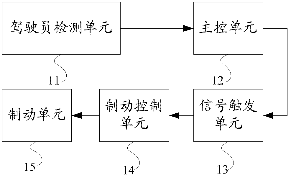
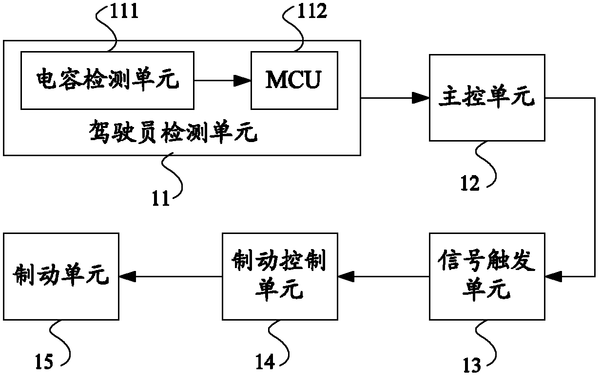
[0024] Embodiment 1 of the present invention provides an EPB system. In this embodiment, the driver detection unit 11 is a capacitive sensing unit, and the capacitive sensing unit is composed of a capacitive detection unit 111 and an MCU 112. Make up the PCB. The capacitive sensing unit in this embodiment is arranged under the driver's seat of the car. figure 2 It is a schematic structural diagram of the EPB system provided by Embodiment 1 of the present invention.
[0025] Wherein, the capacitance detection unit 111 is used to collect the capacitance value above the driver's seat; the MCU 112 is used to judge whether there is a driver on the driver's seat according to the capacitance value collected by the capacitance detection unit 111 . In addition, the electrical signal triggered by the signal trigger unit 13 may be an analog signal or a digital signal.
[0026] In this embodiment, the main control unit 12 is used to determine whether the driver has left the driver's se...
Embodiment 2
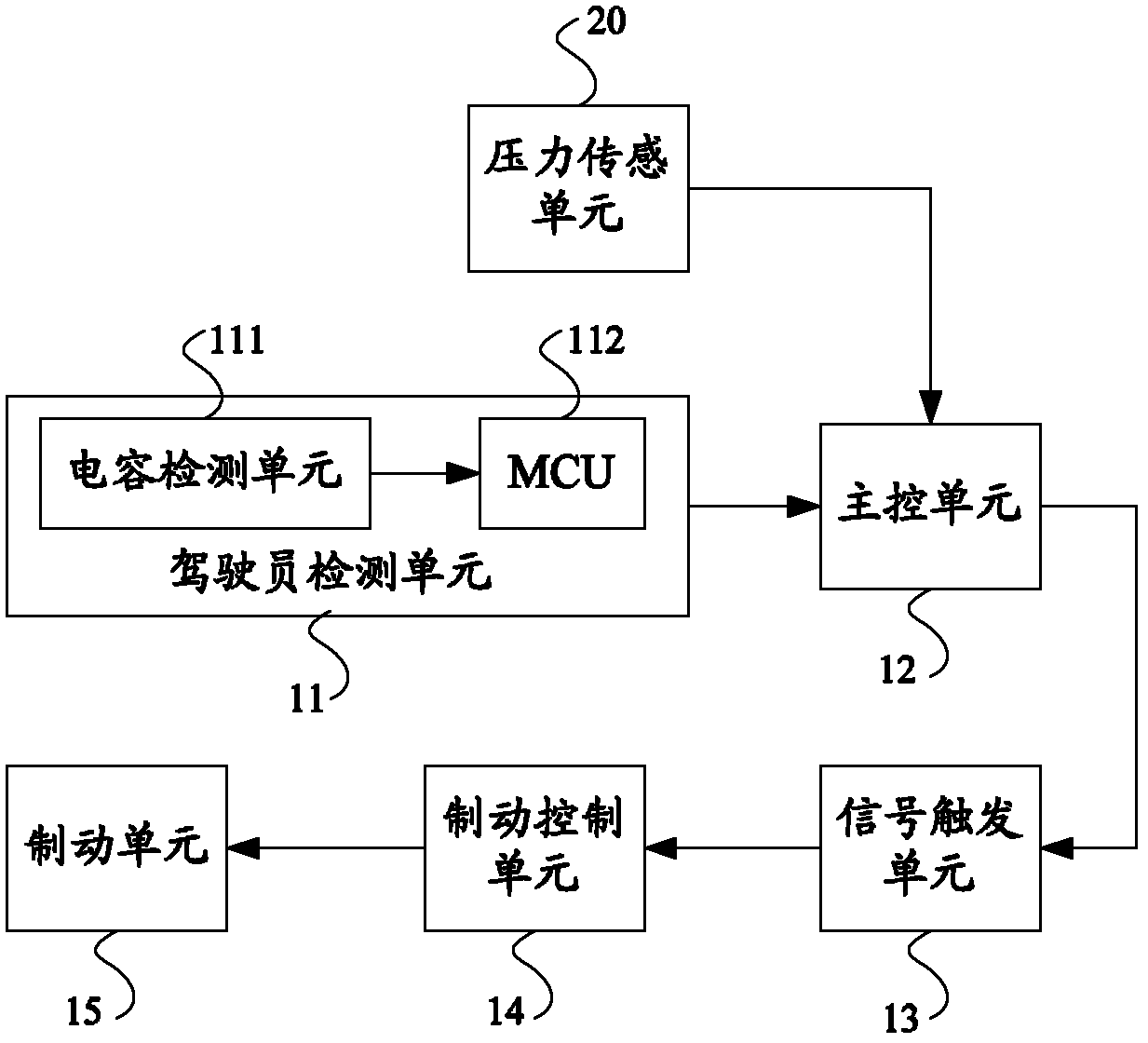
[0031] Embodiment 2 of the present invention provides an EPB system, image 3 The structural diagram of the EPB system provided by the embodiment of the present invention, the system includes the pressure sensing unit 20 in addition to the units in the first embodiment.
[0032] Wherein, the pressure sensing unit 20 is used to collect the pressure value of the driver's seat and judge whether it is an adult's weight according to the collected pressure value.
[0033] In this embodiment, the signals output by the pressure sensing unit 20 and the capacitive sensing unit are all input to the main control unit 12. When the MCU 112 of the capacitive sensing unit determines that there is a driver on the driver's seat, the pressure sensing unit 20 After judging the weight of an adult according to the pressure value, if the main control unit 12 judges that the driver on the driver's seat leaves according to the capacitance value and / or the voltage value changes, the control signal trig...
PUM
 Abstract
Description
Claims
Application Information