
Pulley system of variable power crane hoisting hook and integrated system thereof

A technology of cranes and hooks, applied in the direction of load block, load hanging components, transportation and packaging, etc., can solve the problems of heavy workload, cost increase, waste, etc., and achieve the effect of small workload

Inactive Publication Date: 2012-07-04
QINGDAO HAIXI HEAVY DUTY MASCH CO LTD
View PDF12 Cites 12 Cited by
  • Summary
  • Abstract
  • Description
  • Claims
  • Application Information

AI Technical Summary

Problems solved by technology

[0002] The magnification of the lifting hook block of the existing cranes is generally unchanged, and the magnification of the lifting hook block is usually selected according to the maximum lifting capacity and speed of the crane, but in heavy cranes, the maximum lifting capacity is often Least used, only occasionally, most used less than a few times a year
However, the lower lifting capacity is often used, but the speed is limited by the magnification of the lifting hook block. The effect of the crane cannot be fully utilized, and the power of the lifting motor cannot be fully utilized, resulting in waste.
[0003] The adjustment of the existing crane hoisting hook pulley magnification is to rewind the steel wire rope. Using this method, the workload of the operator is very large, which affects the utilization rate of the crane, and is often not accepted by users.
And because the magnification is reduced, the extra wire rope needs to be stored in the hoisting winch, so the requirements for the rope capacity of the hoisting winch are increased, and the cost is also increased

Method used


Image

  • Pulley system of variable power crane hoisting hook and integrated system thereof
  • Pulley system of variable power crane hoisting hook and integrated system thereof
  • Pulley system of variable power crane hoisting hook and integrated system thereof

Examples


Embodiment Construction

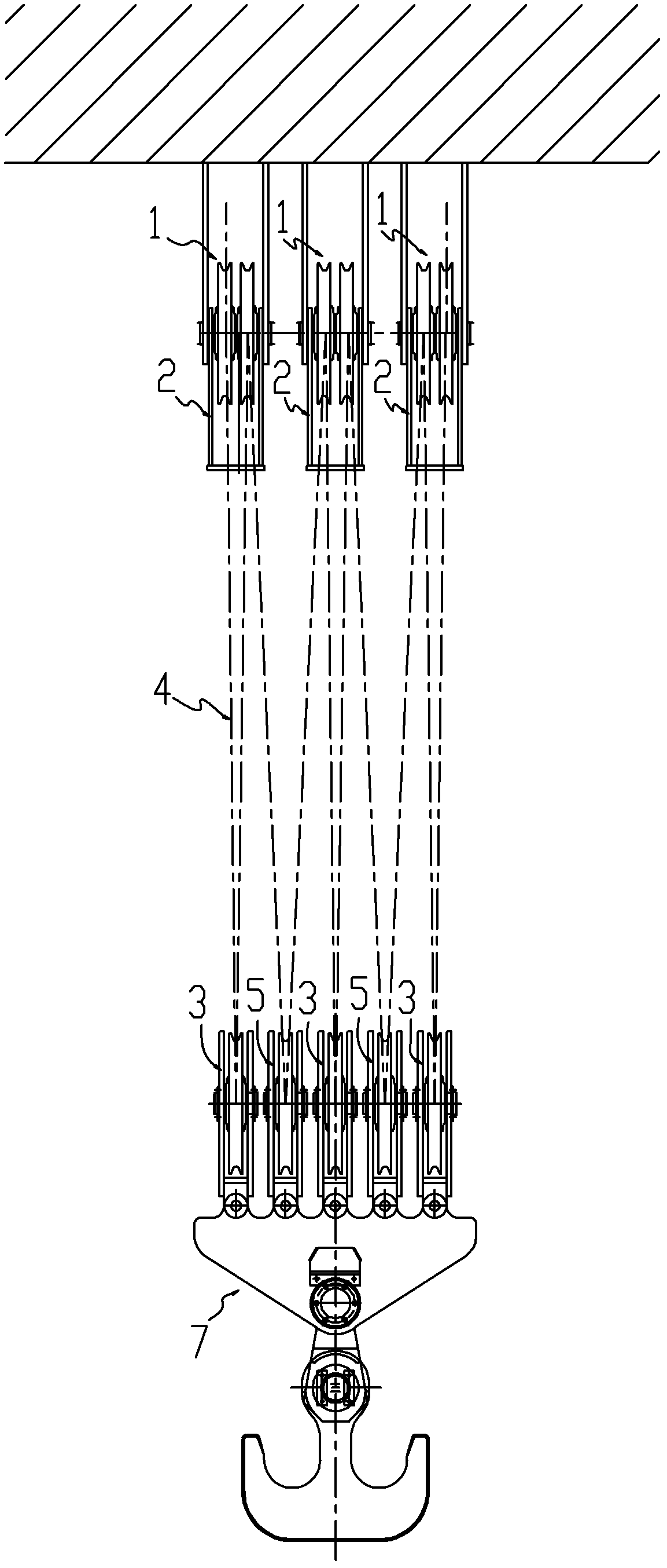
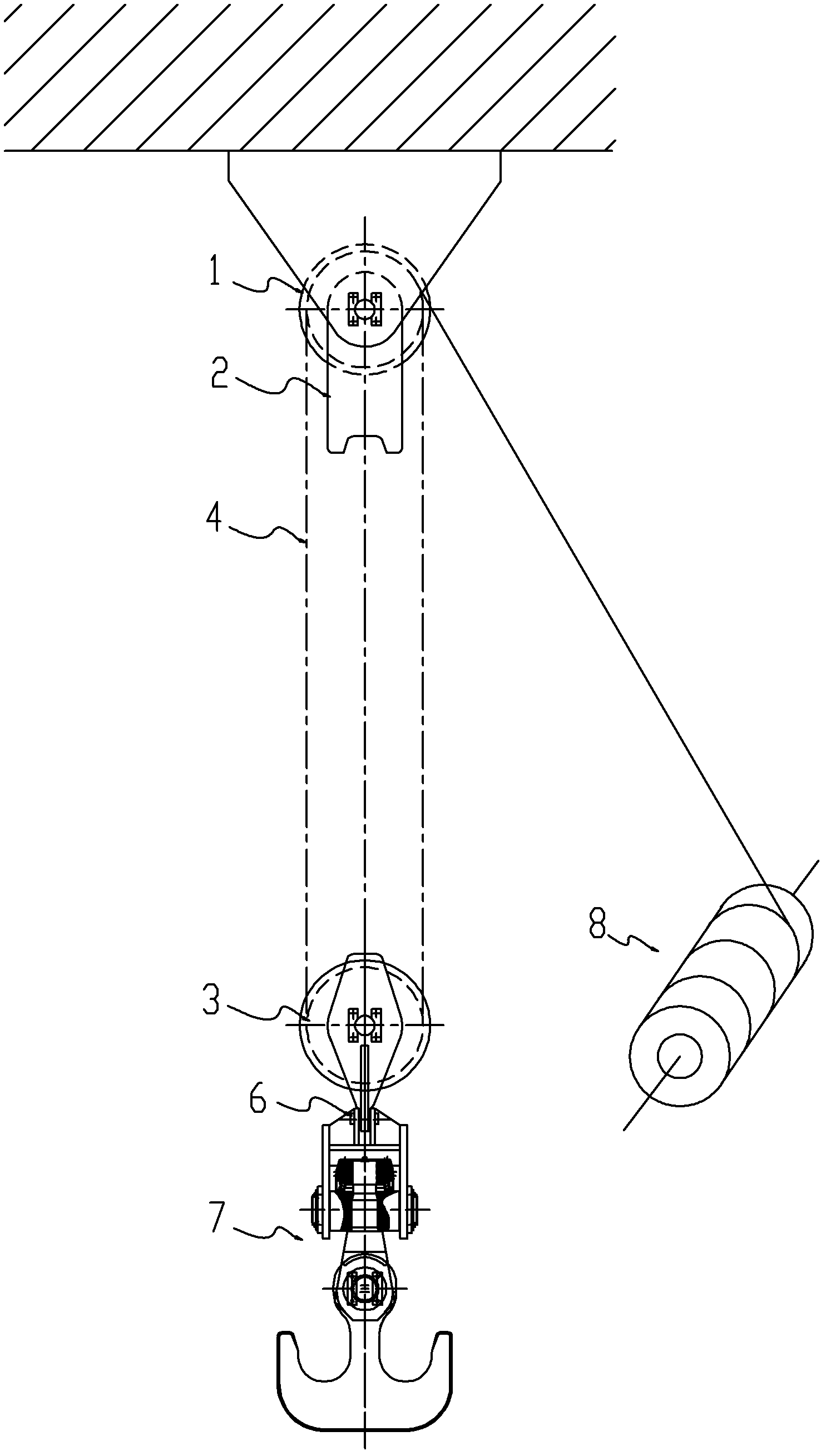
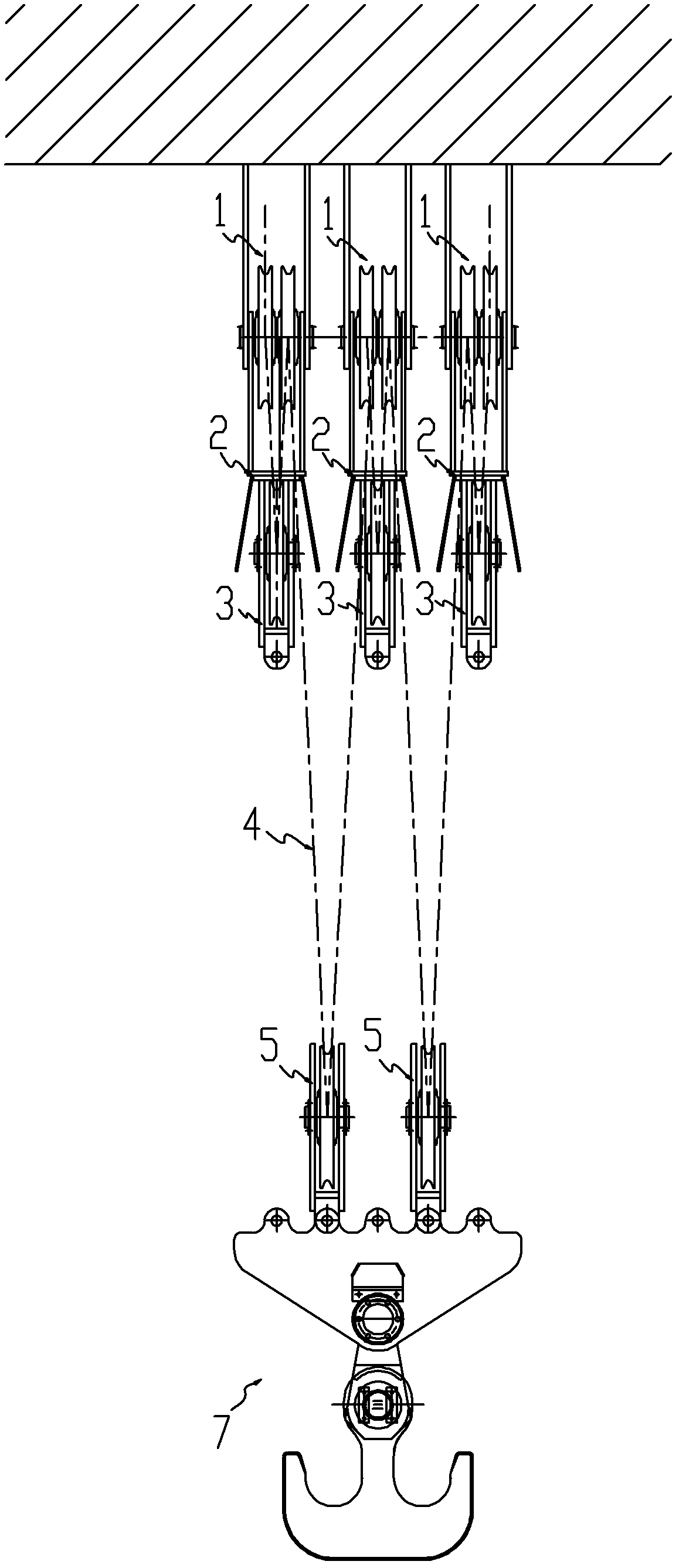
[0024] Combine figure 1 versus figure 2 , A crane variable magnification hoisting hook block system, including a fixed pulley group 1, hook pulley group 5, hook group 7, steel wire rope 4 and hoisting winch 8. The hook pulley group is connected to the hook group, and the wire rope is composed of The hoisting winch starts and winds around the fixed pulley block and hook pulley block. The above hook group is equipped with an adjustable pulley group 3 that can be used as a component of the crane pulley group. A detachable connection structure is adopted between the adjustable pulley group and the hook group. For example, the adjustable pulley group is connected through a connecting pin 6, a shackle, a latch or a card. It is connected to the hook group by way of buckle. The number of adjustable pulley groups mentioned above can be one or more groups. In this example, the number of adjustable pulley groups is three; the number of pulleys in each adjustable pulley group can be one o...


PUM


Abstract

The invention discloses a pulley system of a variable power crane hoisting hook and an integrated system thereof. The pulley system comprises fixed pulley blocks, hook pulley blocks, a hook group, a steel wire rope and a winding winch, wherein the hook pulley blocks are connected onto the hook group; the hook group is configured with maneuverable pulley blocks which can be used as a component of crane pulley blocks, the maneuverable pulley blocks and the hook group adopt a detachable connection structure, a fixed frame of movable pulley blocks with the same number as that of the maneuverable pulley blocks is arranged at the part of the fixed pulley blocks or below the fixed pulley blocks, when the maneuverable pulley blocks are dismantled and released from the hook group, the maneuverable pulley blocks is automatically lifted by the steel wire rope to the fixed frame of the corresponding movable pulley blocks to be fixed, and at the moment, the positions of the fixed maneuverable pulley blocks and the paired fixed pulley are kept relatively unchanged. When the multiplying power of the pulley system is adjusted, the connecting pin and other parts of the maneuverable pulley blocks are only needed to be dismantled, so the workload is small, and the utilization rate of a crane is not influenced.

Description

Technical field [0001] The present invention relates to a hoisting hook block system with variable magnification of a crane. Specifically, the magnification of the hoisting hook block of a crane can be changed and adjusted to adjust different lifting weights and different lifting hooks. Rise speed. Belongs to lifting and transporting machinery. Background technique [0002] The magnification of the hoisting hook block of the existing crane is generally unchanged. Usually, the magnification of the hoisting hook block is selected according to the maximum lifting weight and speed of the crane, but in heavy cranes, the maximum lifting weight is often The least used ones are only occasionally used, and most are used less than a few times a year. However, lower lifting weights are often used, but the speed is limited by the rate of the hoisting hook block. The crane's efficiency cannot be fully utilized, and the power of the lifting motor cannot be fully utilized, resulting in waste....

Claims


Application Information

Patent Timeline
Patent Type & Authority Applications(China)
IPC IPC(8): B66C11/16
Inventor 杨刚梁建平潘海鹰雒金贵程起华谢宛朋
Owner QINGDAO HAIXI HEAVY DUTY MASCH CO LTD
Learn More