Meter assembly, sheath fluid impedance meter and flow cytometer

A technology of counters and components, applied in the field of sheath flow impedance counting devices, can solve the problems of loss of control of liquid level, change of liquid level, no actual connection between the rear sheath and the front sheath, etc., and achieves the effect of improving stability

Active Publication Date: 2012-07-04
SHENZHEN MINDRAY BIO MEDICAL ELECTRONICS CO LTD
View PDF3 Cites 22 Cited by
  • Summary
  • Abstract
  • Description
  • Claims
  • Application Information

AI Technical Summary

Problems solved by technology

[0007] In this way, there is a problem: on the one hand, the rear sheath should not be actually connected to the front sheath; It enters in the way of dripping, and the outlet also flows out in the way of dripping
The first problem is the liquid level initialization problem, that is, how to ensure that the liquid level is within an a

Method used


Image

  • Meter assembly, sheath fluid impedance meter and flow cytometer
  • Meter assembly, sheath fluid impedance meter and flow cytometer
  • Meter assembly, sheath fluid impedance meter and flow cytometer

Examples


Embodiment Construction

[0034] The present invention will be further described in detail below through specific embodiments in conjunction with the accompanying drawings.

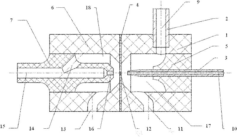
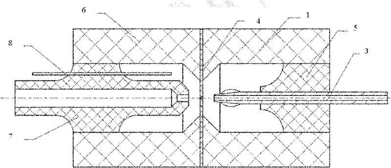
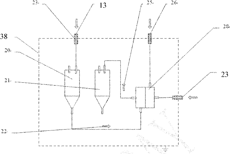
[0035] Such as figure 1 , Figure 4 and Figure 5As shown, the sheath flow impedance counting device in this embodiment includes a counter assembly, a first container 33 and a second container 36 . The counter assembly includes a counter 28 , a rear sheath isolation chamber 20 and a waste fluid isolation chamber 21 . The counter 28 has a forebay 17 , a forebay cleaning inlet 11 , a front sheath inlet 9 and a sample solution inlet 10 , and the forebay cleaning inlet 11 , the front sheath inlet 9 and the sample solution inlet 10 are all in communication with the forebay 17 . The counter also has a rear pool 18 , a rear sheath inlet 13 and a waste liquid outlet 15 , and both the rear sheath inlet 13 and the waste liquid outlet 15 communicate with the rear pool 18 . A partition 4 is provided between the front pool 17 and the rear ...


PUM


Abstract

The invention discloses a meter assembly, a sheath fluid impedance meter and a flow cytometer. The meter assembly comprises a meter, a waste fluid isolation chamber, a back sheath isolation chamber and a pressure balance pipeline, wherein the meter is provided with a front pool, a back pool, a back sheath inlet and a waste fluid outlet; the front pool and the back pool are communicated through a metering hole; both the back sheath inlet and the waste fluid outlet are communicated with the back pool; the back sheath isolation chamber is connected with the back sheath inlet; the waste fluid isolation chamber is connected with the waste fluid outlet; the back sheath isolation chamber is connected with the ambient atmosphere through a gas pipeline; the pressure balance pipeline is connected with the back sheath isolation chamber and the waste fluid isolation chamber; and the pressure balance pipeline is provided with a pressure balance controller for controlling the opening/closing state of the pressure balance pipeline. In the cleaning and metering process, the closed chamber is arranged above the liquid level of the back sheath isolation chamber, thereby enhancing the stability of the liquid level.

Description

technical field [0001] The invention relates to a sheath current impedance counting device. Background technique [0002] Sheath flow impedance counting is a technology commonly used in blood analyzers, and the structure of the key component counter is as follows figure 1 and figure 2 shown, where figure 1 is the vertical section of the counter, figure 2 A horizontal section view of the counter. The counter includes a front cell housing 1 , a cathode 2 , a sample needle 3 , a separator 4 , a sample needle base 5 , a rear cell housing 6 , a capture tube 7 and an anode 8 . The forebay housing 1 forms a forebay 17 , and the forebay housing 1 is also provided with a front sheath inlet 9 , a sample liquid inlet 10 and a forebay cleaning inlet 11 all connected to the forebay 17 . The rear pool housing 6 forms a rear pool 18 , and the rear pool housing 6 is opened with a rear sheath inlet 13 passing through the rear pool 18 . The capture pipe 7 is fixed inside the rear tank...

Claims


Application Information

Patent Timeline
IPC IPC(8): C12M1/34C12Q1/06
CPCG01N15/1209
Inventor 申涛郭文恒滕锦
Owner SHENZHEN MINDRAY BIO MEDICAL ELECTRONICS CO LTD
Why Eureka
Try Eureka