Magnetron sputtering source and magnetron sputtering equipment

A technology of magnetron sputtering and magnetron, which is applied in the field of magnetron sputtering equipment, can solve the problems of affecting the service life of the motor, the effect is not ideal, and the motor control process is complicated, so as to improve the utilization rate and avoid the impact

Active Publication Date: 2012-07-04
BEIJING NAURA MICROELECTRONICS EQUIP CO LTD
View PDF10 Cites 12 Cited by
  • Summary
  • Abstract
  • Description
  • Claims
  • Application Information

AI Technical Summary

Problems solved by technology

Therefore, in order to realize the above-mentioned motor speed regulation method, the motor must be operated at a very high acceleration / deceleration frequency, which not only seriously affects the service life of the motor, but also causes practical application problems due to the complexity of the motor control process. The effect is not ideal

Method used


Image

  • Magnetron sputtering source and magnetron sputtering equipment
  • Magnetron sputtering source and magnetron sputtering equipment
  • Magnetron sputtering source and magnetron sputtering equipment

Examples


Embodiment Construction

[0036] In order to enable those skilled in the art to better understand the technical solution of the present invention, the magnetron sputtering source provided by the present invention and the magnetron sputtering equipment using the magnetron sputtering source will be described in detail below with reference to the accompanying drawings.

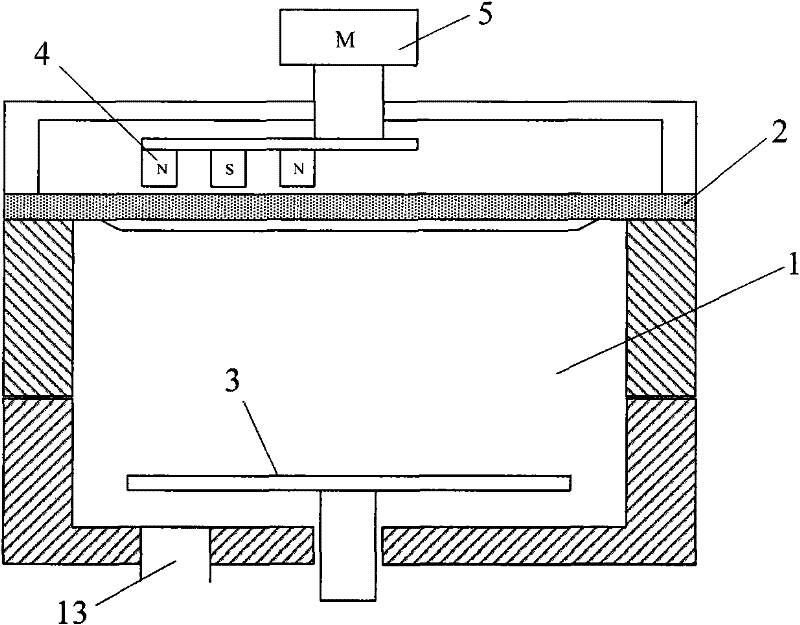
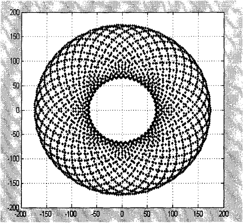
[0037] The magnetron sputtering source provided by the present invention includes a magnetron and a driving device for driving the magnetron. Wherein, the magnetron can scan the entire target area with a helical trajectory under the drive of the driving device.

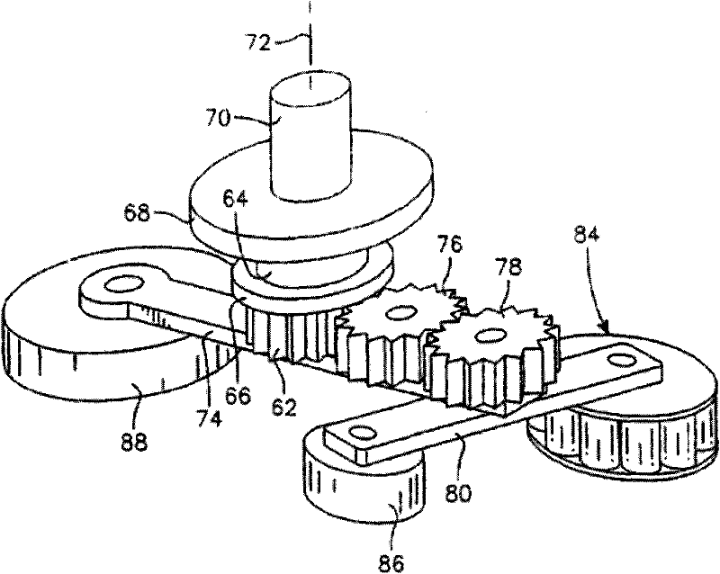
[0038] Specifically, the above-mentioned driving device can be set as a structure including a central shaft, a circumferential rotating part, and a radially moving part; The circumferential rotating part simultaneously drives the radial rotating part and the magnetron to rotate around the central axis, so that the magnetron has a helical running track under the joint action of th...


PUM


Abstract

The invention provides a magnetron sputtering source and magnetron sputtering equipment. The magnetron sputtering source comprises a magnetron and a driving device which are connected, wherein the driving device is used for driving the magnetron to scan the whole target area in a spiral line track, so that when the magnetron sputtering source is applied to a magnetron sputtering process, areas of a target can be effectively sputtered, and a problem that some areas on the target cannot be fully utilized is avoided; and moreover, the retention period of the magnetron in the center and on the edge of the target is effectively adjusted by adjusting the running speed of the driving device, so that the consumption rates of the areas of the target tend to be consistent; and therefore, the utilization rate of the target is effectively improved. The magnetron sputtering equipment also can effectively improve the utilization rate of the target.

Description

technical field [0001] The invention relates to the technical field of microelectronic processing, in particular to a magnetron sputtering source and a magnetron sputtering device using the magnetron sputtering source. Background technique [0002] In the microelectronics industry, as one of the important means of producing integrated circuits, liquid crystal displays, thin-film solar cells and LEDs, magnetron sputtering technology has been highly valued by the majority of manufacturers. [0003] see figure 1 , is a schematic diagram of the structure of a typical magnetron sputtering device. The equipment mainly includes: a process chamber 1 , an electrostatic chuck 3 arranged at the lower position inside the process chamber 1 , a target 2 and a magnetron 4 arranged above the process chamber 1 , and a magnetron drive motor 5 . In addition, an air extraction device 13 is connected to the lower end or the side wall of the process chamber 1 . Its technological process is as ...

Claims


Application Information

Patent Timeline
Patent Type & Authority Applications(China)
IPC IPC(8): C23C14/35
Inventor 刘旭
Owner BEIJING NAURA MICROELECTRONICS EQUIP CO LTD
Why Eureka
Try Eureka