Through prestress steel truss and concrete combined continuous steel structure bridge and construction method thereof

A technology of prestressed steel and prestressed steel strands, which is applied in the field of down-loaded prestressed steel truss-concrete composite continuous rigid frame bridges and construction fields, and can solve the problem of steel truss-concrete composite continuous rigid frame bridges with extremely large spans. Construction, bridge building height restrictions and other issues, to achieve reliable long-term structural performance, reduce self-weight, and avoid long-term excessive deflection

Inactive Publication Date: 2012-07-04
CCCC CIVIL ENG SCI & TECH +1
View PDF10 Cites 14 Cited by
  • Summary
  • Abstract
  • Description
  • Claims
  • Application Information

AI Technical Summary

Benefits of technology

This patented technology describes an improved way to construct reinforced composite frames that have better strength at high temperatures without adding too much material or requiring complicated processes like bolting. It also reduces the amount needed when installing these structures while maintain their integrity during use. Overall, this new design improves safety, durability, efficiency, flexibility, and cost effectiveness.

Problems solved by technology

This patented technical problem addressed in this patents relates to improving the durability and flexiblality of continuously reinforced hardened frames (CSTR) cast over large sections called Continuous Reinforce Frame Bridge(CRB). While current methods such as weld joining tend towards issues like cracking due to thermal stresses caused during curling processes, they require expensive equipment and complicated procedures. Additionally, existing techniques involve heavy lifting operations and may lead to instabilities when erected vertically across inclined slopes.

Method used


Image

  • Through prestress steel truss and concrete combined continuous steel structure bridge and construction method thereof
  • Through prestress steel truss and concrete combined continuous steel structure bridge and construction method thereof
  • Through prestress steel truss and concrete combined continuous steel structure bridge and construction method thereof

Examples


Embodiment Construction

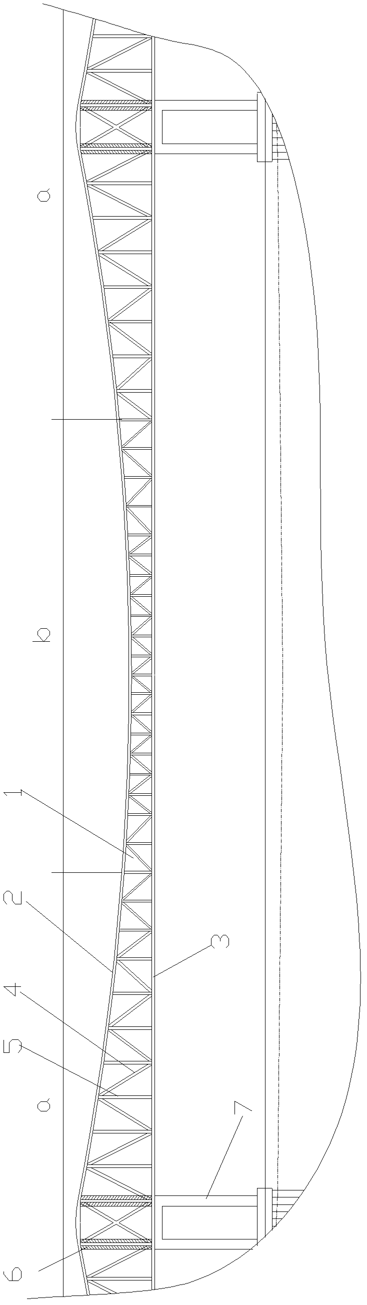
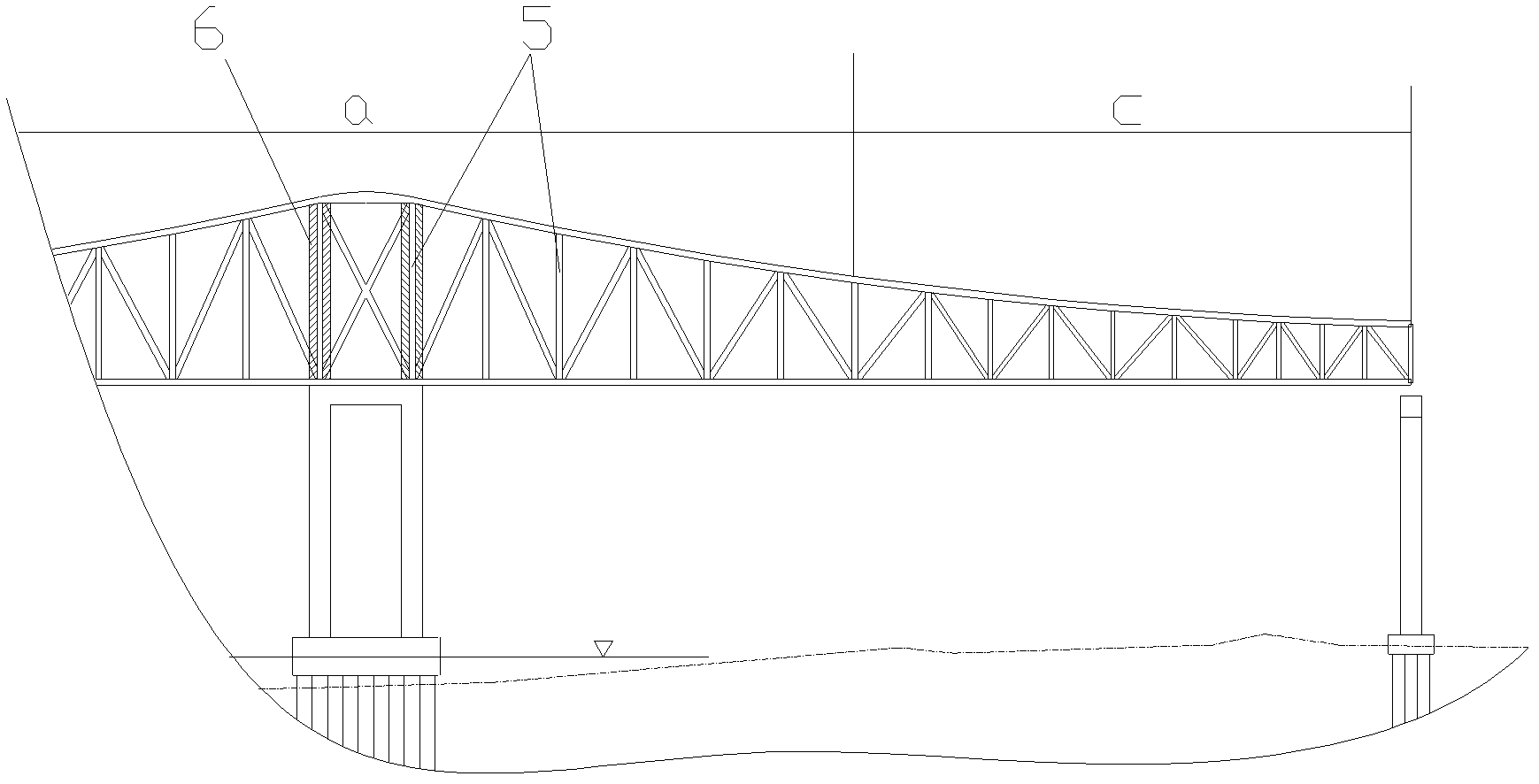
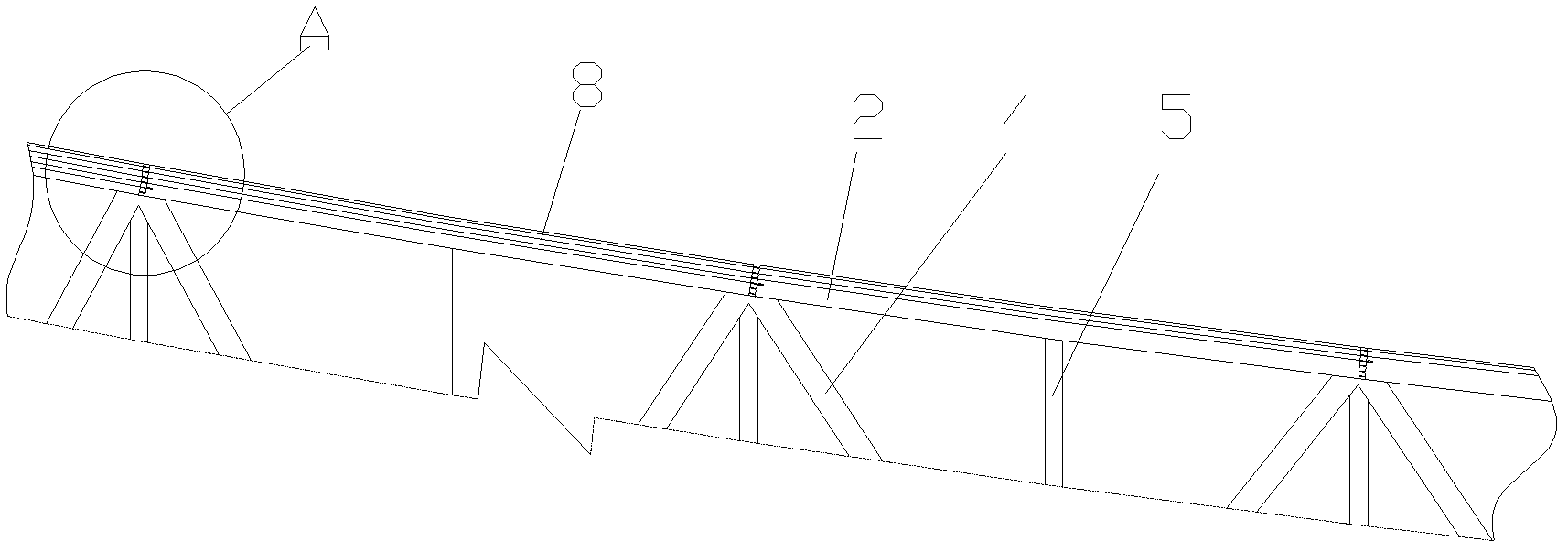
[0040] figure 1 It is a schematic diagram of the main structure of the bridge of the present invention, figure 2 It is a schematic diagram of the main girder side span structure of the present invention, image 3 is the structural diagram of prestressed steel tendons in the upper chord of the main girder close to the bridge pier bearing negative bending moment, Figure 4 It is a schematic diagram of the mid-span beam section of the main girder bearing positive bending moment between adjacent bridge piers, Figure 5 for image 3 Enlarged view at A, Figure 6 is the cross-section diagram of the upper chord of the steel truss girder subjected to negative bending moment near the bridge pier, Figure 7 is the cross-sectional view of the main girder section near the middle pier bearing negative bending moment, Figure 8 is the cross-sectional view of the main girder section bearing positive bending moment in the mid-span between adjacent piers, Figure 9is the cross-sectional...


PUM


Abstract

The invention discloses a through prestress steel truss and concrete combined continuous steel structure bridge and a construction method of the bridge. Upper chord members and lower chord members of a steel truss beam are respectively in hollow structures, vertical prestress steel bundles are arranged inside the upper chord members of the steel truss beam for bearing the hogging moment, concrete is filled inside the lower chord members, concrete bottom plates are formed between the lower chord members in a cast-in-situ way, the concrete is filled in the upper chord members of the steel truss beam for bearing sagging moment, the lower chord members are fixedly connected for forming steel bridge panels, and the concrete bottom plates and the steel bridge panels form bridge surface bases. The concrete consumption is obviously reduced, because the bridge surface is positioned in a position corresponding to the lower chord rods, the steel structure bridge has higher universality and can be applicable to environment with confliction in height differences between the headway and the pavement at two ends of the bridge, the bridge surface height can be reduced and regulated according to environment requirements, the navigation under the bridge and the smooth butt joint between the bridge surface and the pavements at two ends can be ensured, great construction transformation on the pavements at two ends is avoided, and the construction cost is greatly saved.

Description


Claims


Application Information

Patent Timeline
Owner CCCC CIVIL ENG SCI & TECH
Why Eureka
Try Eureka