Turbocharger with divided turbine housing and annular rotary bypass valve for the turbine

一种涡轮增压器、涡轮壳体的技术,应用在阀装置、滑动阀、机器/发动机等方向,能够解决难阀完全、回转阀或提升阀可控性差、发动机系统瞬态响应差等问题,达到好可控性的效果

Active Publication Date: 2012-07-04
GARRETT MOTION TECH (SHANGHAI) CO LTD
View PDF10 Cites 20 Cited by
  • Summary
  • Abstract
  • Description
  • Claims
  • Application Information

AI Technical Summary

Problems solved by technology

One disadvantage associated with this arrangement is that it is difficult to fully seal the valve in the closed position as air pressure tends to open the valve
Leakage through a closed bypass valve is the cause of a reduction in the performance of the turbine and thus the turbocharger and its associated engine
A typical solution to the leakage problem is to preload the bypass valve member against the valve seat, but this often does not completely eliminate the leakage and in any case it leads to additional problems such as an increase in the actuation force required to open the valve
[0005] In addition, rotary or poppet valves tend to be poor in controllability, especially in the crack-open position, and in general, bypass flow rate is highly non-linear with valve position, making proper adjustment of bypass Throughflow rate is very difficult
This leads to problems such as poor transient response of turbochargers and engine systems

Method used


Image

  • Turbocharger with divided turbine housing and annular rotary bypass valve for the turbine
  • Turbocharger with divided turbine housing and annular rotary bypass valve for the turbine
  • Turbocharger with divided turbine housing and annular rotary bypass valve for the turbine

Examples


Embodiment Construction

[0035] The present disclosure will now be described more fully hereinafter with reference to the accompanying drawings, in which some, but not all embodiments of the inventions are shown. Indeed, these inventive concepts may be embodied in many different forms and should not be construed as limited to the embodiments described herein; rather, these embodiments are provided so that this disclosure will satisfy applicable statutory requirements. Like numbers refer to like elements throughout.

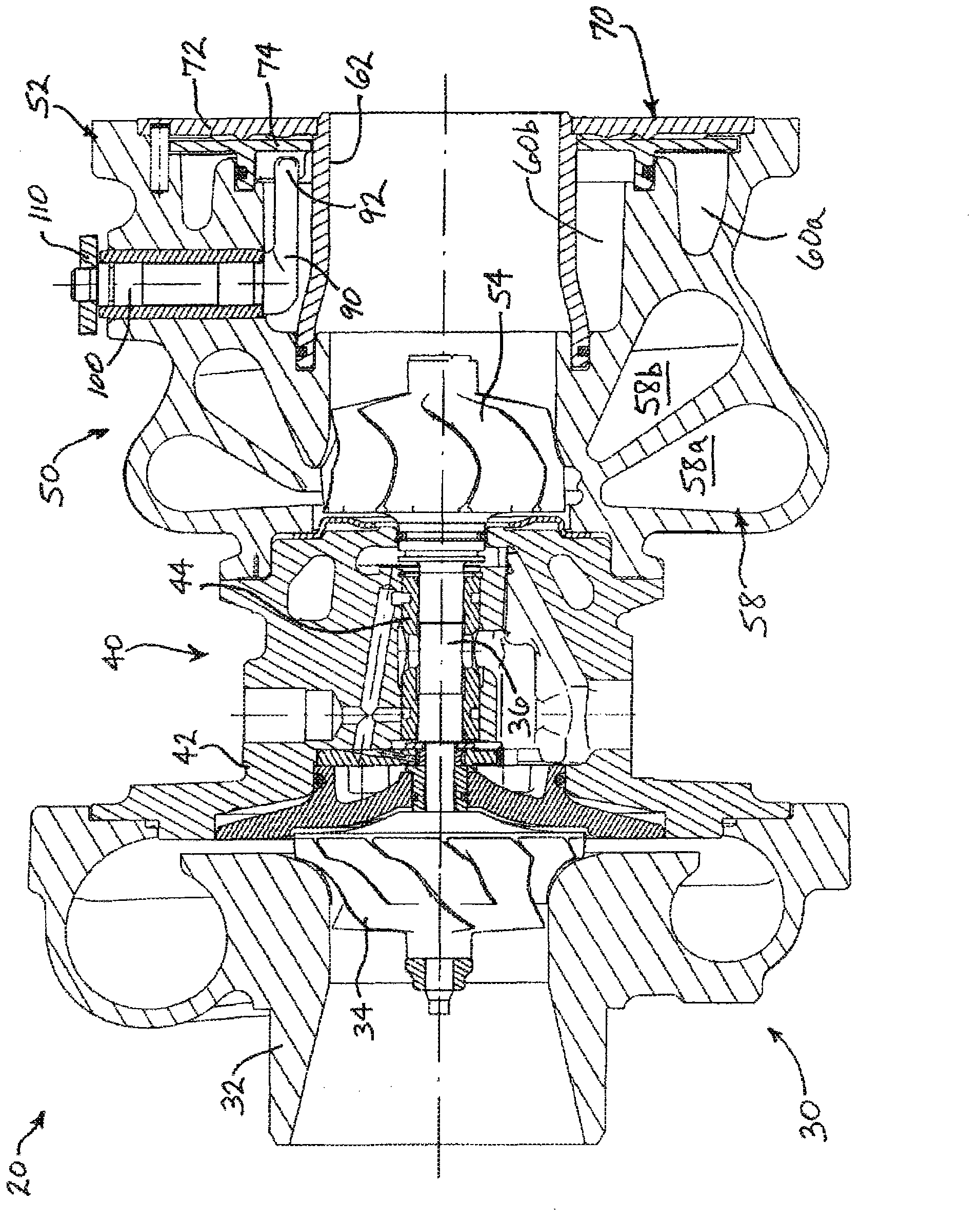
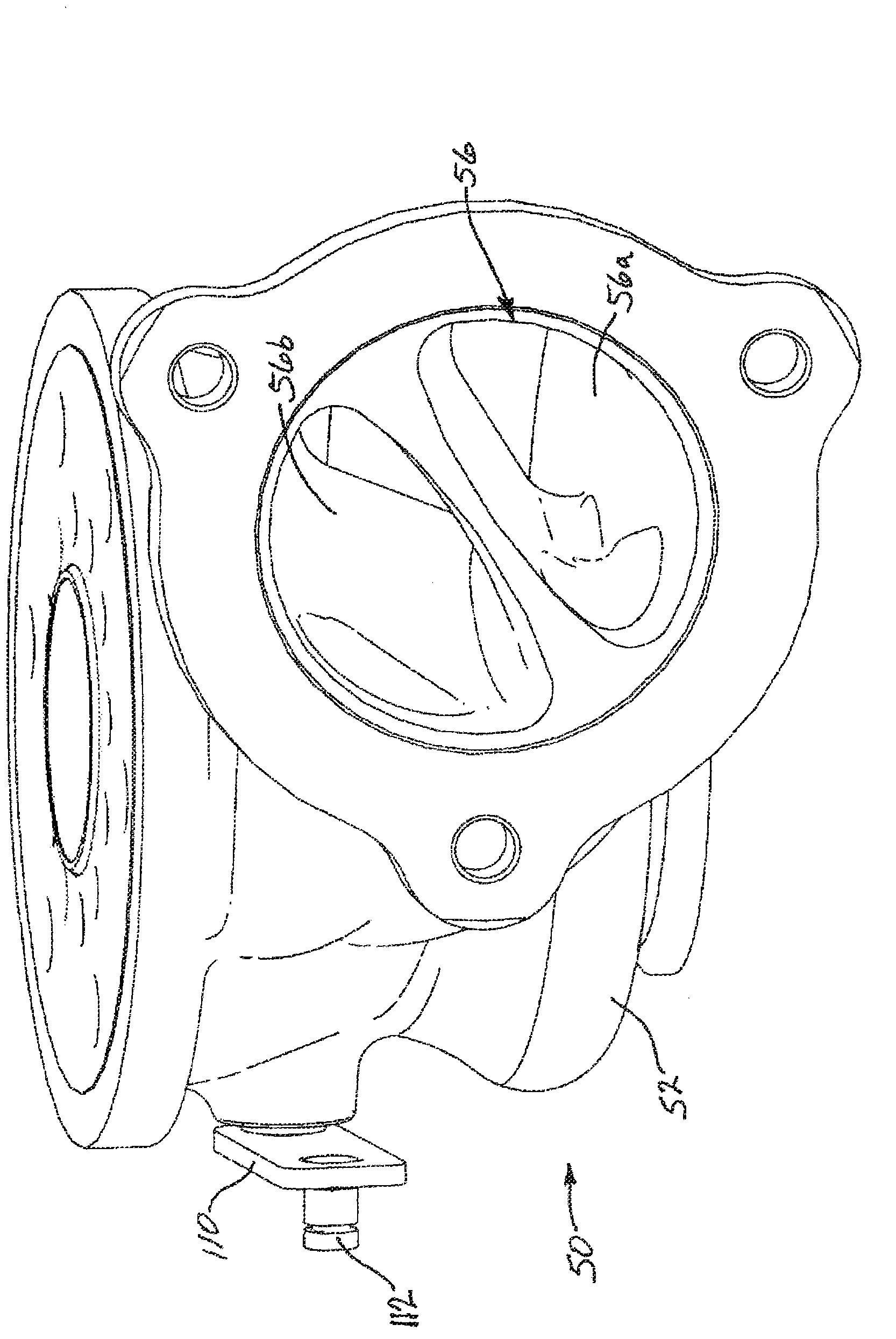
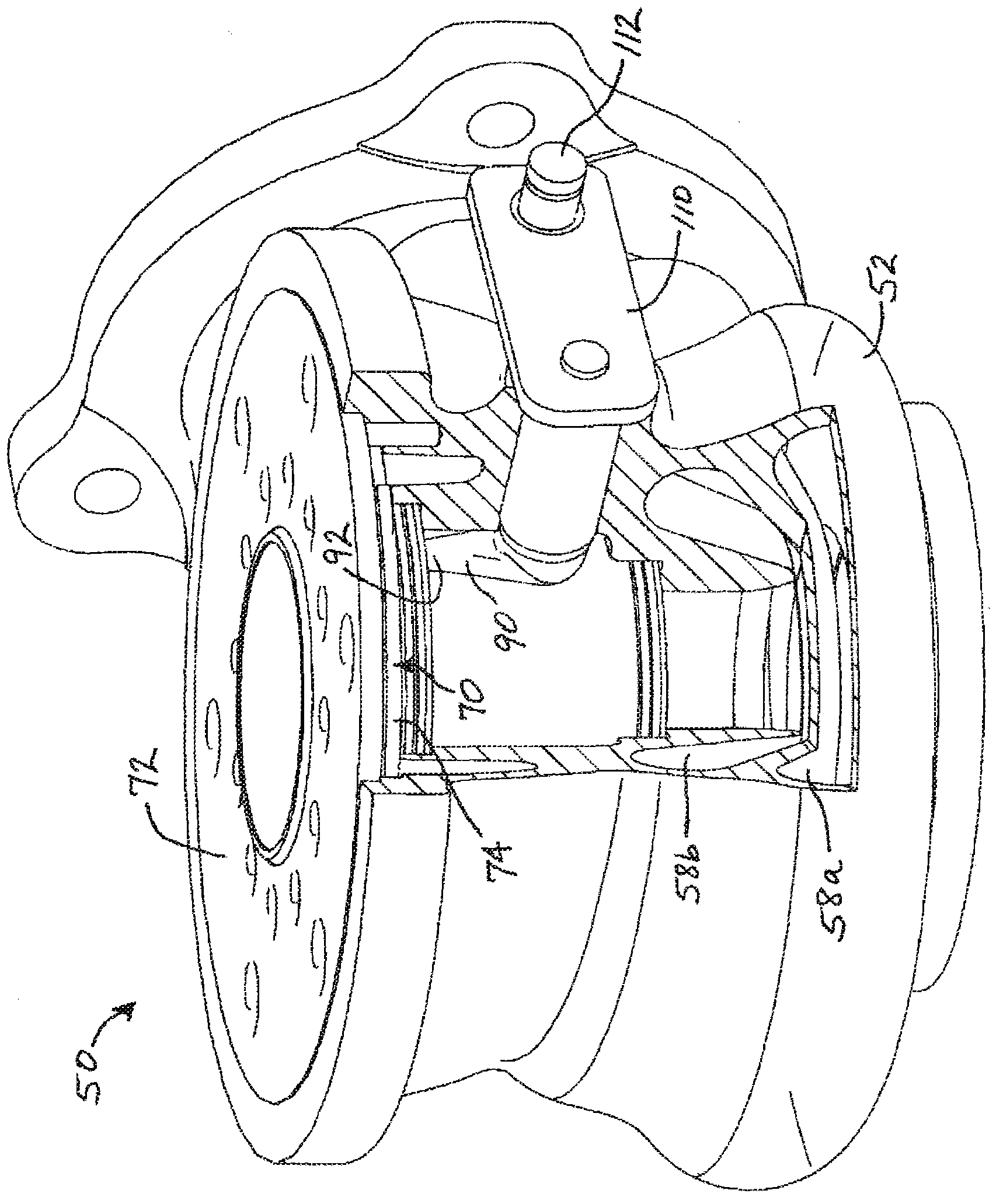
[0036] The turbocharger 20 according to one embodiment of the present invention is figure 1is shown in axial section in , and various views of a turbine assembly and components of a turbine assembly for a turbocharger are in Figure 2-13 shown in . Such as figure 1 As shown, the major subassemblies of turbocharger 20 include compressor assembly 30 , intermediate housing assembly 40 , and turbine assembly 50 . Compressor assembly 30 includes a compressor housing 32 and a compressor whe...


PUM


Abstract

The invention provides a turbocharger with a divided turbine housing and an annular rotary bypass valve for a turbine. The turbocharger includes a turbine wheel mounted within a turbine housing and connected to a compressor wheel by a shaft. The turbine housing defines an exhaust gas inlet connected to a divided volute that surrounds the turbine wheel, and an axial bore through which exhaust gas that has passed through the turbine wheel is discharged from the turbine housing. The turbine housing further defines a pair of concentric annular bypass passages surrounding the bore and arranged to allow exhaust gas to bypass the turbine wheel as two separate bypass streams. An annular bypass valve is disposed in the bypass passage. The bypass valve comprises a fixed annular valve seat and a rotary annular valve member arranged coaxially with the valve seat. The valve member is disposed against the valve seat and is rotatable about the axis for selectively varying a degree of alignment between respective orifices in the valve seat and valve member.

Description

[0001] Cross References to Related Applications [0002] This application is related to U.S. Patent Application Serial No. 12 / 611,816, filed November 3, 2009, and U.S. Patent Application Serial No. 12 / 711,434, filed April 30, 2010, the entire contents of which are hereby incorporated by reference incorporated into this article. technical field [0003] The present disclosure relates to an exhaust driven turbocharger having a split turbine housing for two independent exhaust streams supplied to the turbine. The present disclosure more particularly relates to bypass devices that allow exhaust gas to bypass a turbine under certain engine operating conditions. Background technique [0004] In a conventional turbocharger, the turbine housing defines a bypass duct, usually on the side of the main bore through the housing, and the bypass duct is connected via a bypass valve to the exhaust inlet or to the volute of the housing . Bypass valves are typically rotary or poppet type v...

Claims


Application Information

Patent Timeline
Patent Type & Authority Applications(China)
IPC IPC(8): F02B37/18F01D25/24
CPCF01D25/24F02B37/183F01D17/105F05D2220/40F02B37/00Y02T10/144F01D9/026F05D2230/90F05D2240/55F05D2250/411F05D2260/606F16K3/085Y02T10/12
Inventor A·隆巴N·塞里斯M·帕拉尼亚潘A·H·切拉亚
Owner GARRETT MOTION TECH (SHANGHAI) CO LTD
Why Eureka
Try Eureka