Trigger signal control engine decompression device

A trigger signal and engine technology, applied in engine control, machine/engine, mechanical equipment, etc., can solve the problems of engine fuel consumption, high temperature rise, short gliding distance, etc., and achieve the effect of prolonging gliding distance and remarkable effect

Active Publication Date: 2013-12-18
南通硕伦实业有限公司
View PDF4 Cites 0 Cited by
  • Summary
  • Abstract
  • Description
  • Claims
  • Application Information

AI Technical Summary

Problems solved by technology

[0002] Gasoline internal combustion engines generally use carburetors to supply oil, which accounts for the vast majority. This mechanism has a simple structure and is easy to maintain, but it has obvious shortcomings: the vehicle needs to constantly change the opening angle of the accelerator under different road conditions to change The speed of the engine, when transitioning from high speed to low speed, the throttle valve is loosened to the lowest position, but the speed of the engine is greater than the opening of the throttle valve, and the strong negative pressure generated by the throat makes the idle nozzle of the carburetor and the main nozzle The fuel injection volume is several times higher than the normal value, resulting in unnecessary fuel consumption of the engine. At the same time, especially for scooters, due to the compression resistance of the engine, the sliding distance is short, the temperature rises high, and it is easy to wear and other disadvantages.

Method used


Image

  • Trigger signal control engine decompression device

Examples


Embodiment Construction

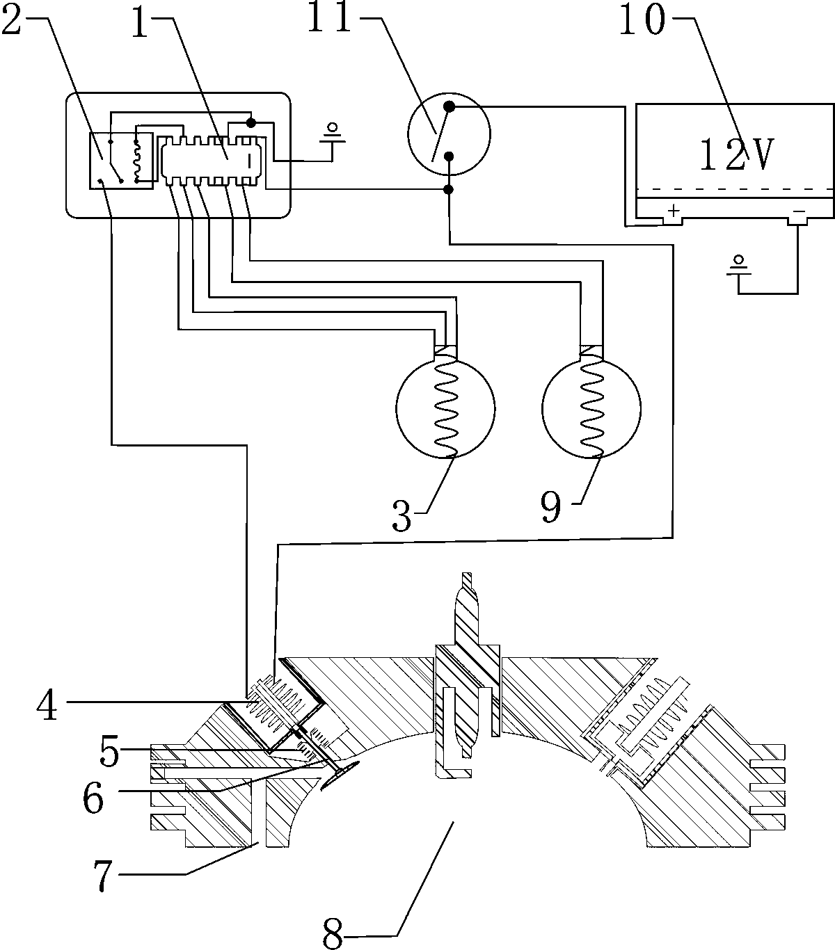
[0008] figure 1 It is a structural diagram of the trigger signal control engine decompression device of the present invention, and its structure is composed of a control chip 1, a relay 2, an accelerator position switch 3, and a motor 4. exist figure 1 Among them, the No. 1 pin and No. 2 pin of the control chip 1, the positive pole line of the motor 4 are connected in parallel with the output end of the power switch 11, and the input end of the power switch 11 is connected with the positive pole of the storage battery 10. The No. 13 pin of the control chip 1, The fourteenth pin is connected to one end of the trigger 9, and the other end of the trigger 9 is connected in parallel with the fifteenth and sixteenth pins of the control chip 1, and the sixth and seventh pins of the control chip 1 are respectively connected to the two pins of the relay 2. The coil end is connected, the eighth, ninth and tenth pins of the control chip 1 are respectively connected with the three ends o...


PUM


Abstract

The invention relates to a trigger signal control engine decompression device. The device comprises a control chip, a relay, a throttle position switch and a motor, wherein when an engine works, a signal of a trigger and a signal of the throttle position switch are input into the control chip in a balance mode, or when the throttle position switch is turned off, namely in a normal acceleration state, the control chip determines that the engine normally works and does not send any instruction, and the motor stops working; and under the condition that the engine is decelerated, namely when the signal of the trigger is higher than 1,200rpm and the throttle position switch is turned on, the control chip sends a signal to the relay, the relay is operated, the motor pushes a gas inlet valve to move downwards, compressed gas of the engine is completely discharged from the gas inlet valve, and the engine loses compression pressure and stops working, so that the sliding distance of a vehicle is increased, the suction of fuel oil is stopped, a carburetor engine can save oil by over 10 percent, and an obvious effect is achieved.

Description

technical field [0001] The invention relates to a motor vehicle engine compression and decompression device, in particular to a trigger signal control engine decompression device. Background technique [0002] Gasoline internal combustion engines generally use carburetors to supply oil, which accounts for the vast majority. This mechanism has a simple structure and is easy to maintain, but it has obvious shortcomings: the vehicle needs to constantly change the opening angle of the accelerator under different road conditions to change The speed of the engine, when transitioning from high speed to low speed, the throttle valve is loosened to the lowest position, but the speed of the engine is greater than the opening of the throttle valve, and the strong negative pressure generated by the throat makes the carburetor idle nozzle and main nozzle The fuel injection volume of the scooter is several times higher than the normal value, resulting in unnecessary fuel consumption of th...

Claims


Application Information

Patent Timeline
Patent Type & Authority Patents(China)
IPC IPC(8): F02D13/08
Inventor 傅小理
Owner 南通硕伦实业有限公司
Why Eureka
Try Eureka