Energy-saving automatic speed control system of light motorcycle

A light motorcycle, automatic transmission technology, applied in bicycle gear transmission mechanism, bicycle accessories, transportation and packaging, etc., can solve the problems that the fuel-saving potential of the engine cannot be fully utilized, the energy-saving requirements cannot be met, and the driver's labor intensity is high. Achieve good cushioning, compact structure, and reduce weight

Inactive Publication Date: 2013-07-24
JILIN UNIV
View PDF5 Cites 0 Cited by
  • Summary
  • Abstract
  • Description
  • Claims
  • Application Information

AI Technical Summary

Problems solved by technology

[0005] First, the labor intensity of the driver is relatively high
Every time you shift gears, you need to go through the operation of cutting off the accelerator-pulling the clutch-engaging gear-releasing the clutch-refueling, which not only easily causes driving fatigue, but also needs to divert the driver's attention, which is prone to accidents
[0006] Second, every shift requires an interruption of power
Different drivers are used to shifting gears at different engine speeds or vehicle speeds, and the economical working range of the engine is certain, which means that when driving at different vehicle speeds, the transmission ratio of the transmission device may not be able to make the driving resistance and the engine The most economical load - the speed range matches, and the engine's fuel-saving potential cannot be fully utilized
[0008] Fourth, additional kinetic energy is consumed by the power train when coasting on a cut-off
Therefore, this traditional transmission system cannot make good use of the inertia of the motorcycle for sliding, causing unnecessary wear and tear of parts and energy loss, and cannot meet the increasingly stringent energy-saving requirements of today's society.

Method used


Image

  • Energy-saving automatic speed control system of light motorcycle
  • Energy-saving automatic speed control system of light motorcycle
  • Energy-saving automatic speed control system of light motorcycle

Examples


Embodiment Construction

[0028] The present invention is described in detail below in conjunction with accompanying drawing:

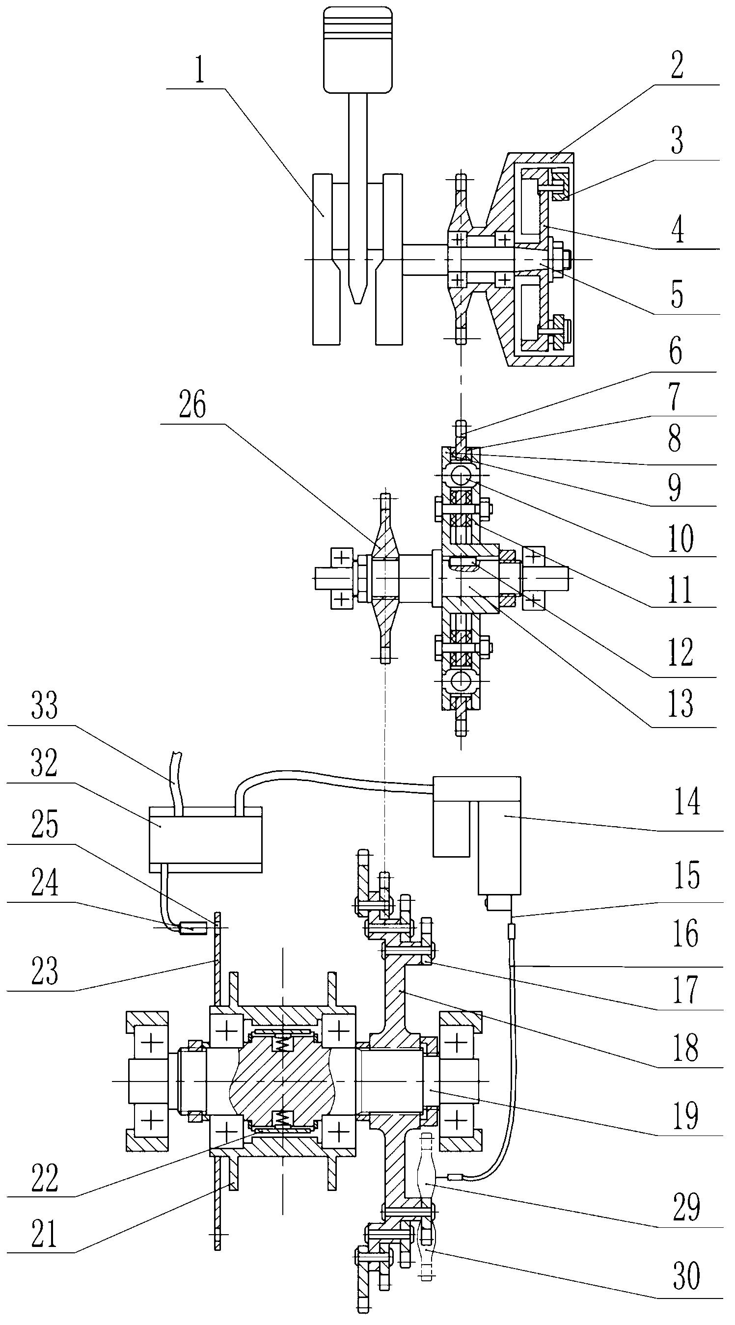
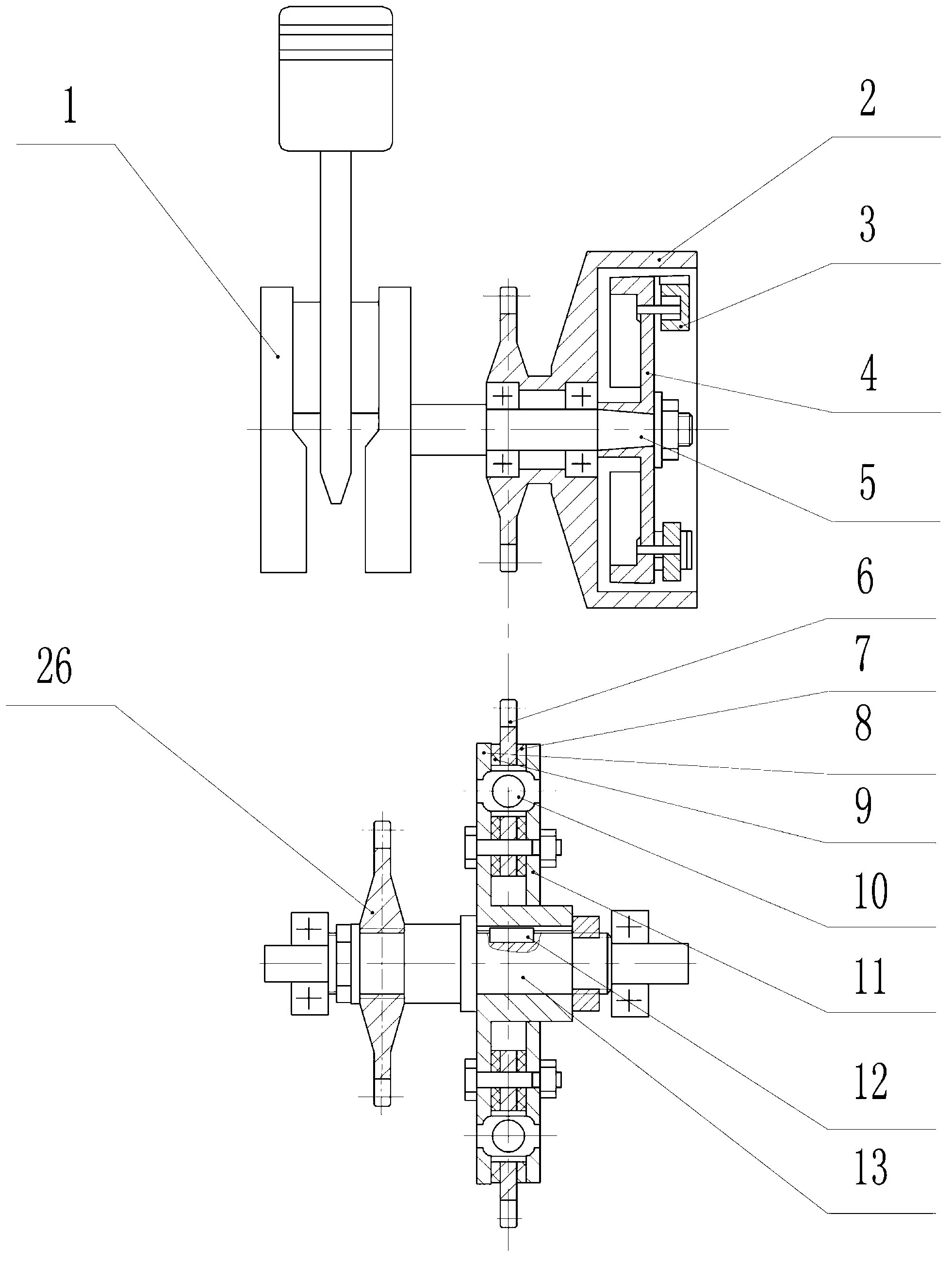
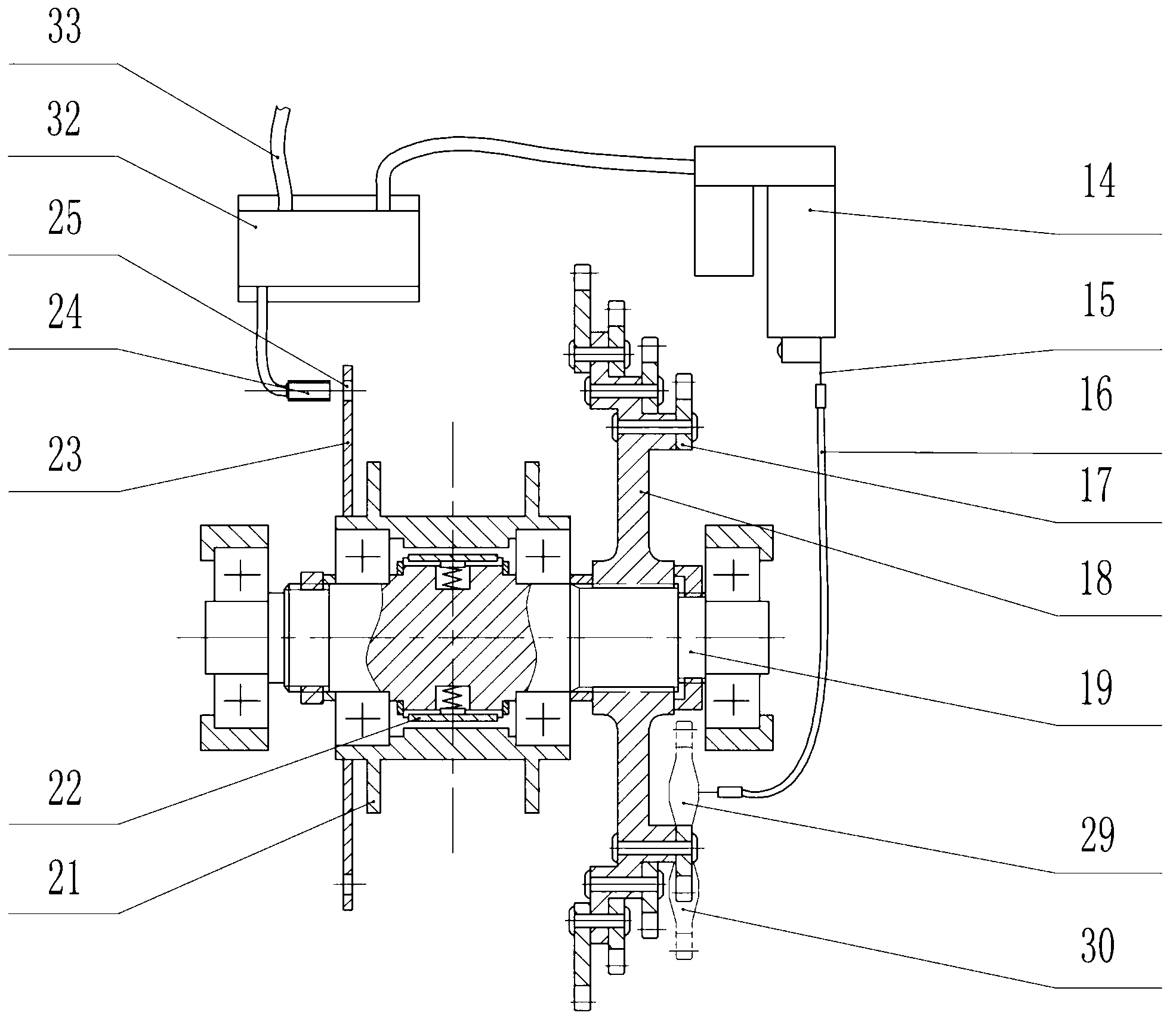
[0029] refer to figure 1 , Figure 4 and Figure 5 , The light motorcycle energy-saving automatic transmission system of the present invention is composed of a centrifugal flying block clutch, a primary reduction device, a secondary reduction device, an automatic transmission control device, and a rear axle assembly.

[0030] The power of the engine 1 is transmitted to the centrifugal flyweight clutch through the crankshaft output shaft 5, and then transmitted to the torsional shock absorber through the primary chain 27, and then the intermediate shaft 13 and the intermediate sprocket 26 transmit the power to the transmission chain through the secondary chain 28 The wheel set 17 drives the rear axle 19, and finally the power is output to the rear hub 21 through the overrunning clutch to drive the motorcycle forward. The present invention adopts a two-stage chain transmissio...


PUM


Abstract

The invention discloses an energy-saving automatic speed control system of a light motorcycle. The energy-saving automatic speed control system comprises a centrifugal fly-block type clutch, a primary reduction gear, a secondary reduction gear, an automatic variable speed control device and a rear shaft assembly. The centrifugal fly-block type clutch is mounted on an output shaft of an engine; the rear shaft assembly and the primary reduction gear are mounted on a frame; and the primary reduction gear is connected with the centrifugal fly-block type clutch. The secondary reduction gear comprises a secondary chain, a variable speed chain wheel set, a chain wheel hub and an intermediate chain wheel, wherein the variable speed chain wheel set is mounted on the right end of a rear shaft in the rear shaft assembly through the chain wheel hub; the intermediate chain wheel is mounted on the left end of an intermediate shaft of the primary reduction gear; and the secondary chain connects the variable speed chain wheel set and the intermediate chain wheel. The automatic variable speed control device comprises an electronic control unit, an accelerator switch sensor, an electric push rod, an electric push rod displacement sensor, a variable speed steel wire and a derailleur. The electronic control unit is respectively connected with a speed measuring device, the accelerator switch sensor, the electric push rod and the electric push rod displacement sensor by using wires.

Description

technical field [0001] The invention relates to a transmission system of a light motorcycle, more precisely, the invention relates to an energy-saving automatic transmission system of a light motorcycle. Background technique [0002] Today, the main form of transmission system in the motorcycle market is the gear type stepped transmission system. The gear-type stepped transmission system achieves the purpose of speed change by changing the meshing of different gear pairs in the gearbox. This variable speed system has been widely used because of its advantages, but there are still certain disadvantages. [0003] From the structural analysis, in the gear-type stepped transmission system, a pair of gears that mesh with each other is required for each gear, which makes the weight of the vehicle larger, the structure of the gearbox is complicated, the design is difficult, and the manufacturing accuracy is high. Costs rise. Moreover, when the engine transmits power to the rear ...

Claims


Application Information

Patent Timeline
Patent Type & Authority Patents(China)
IPC IPC(8): B62M25/08
Inventor 李静曾忠敏丁天威徐潘龙王鹏钱丁超郑伟
Owner JILIN UNIV
Why Eureka
Try Eureka