Tool for removing tripmine quickly

A fast and tool-based technology, applied in the direction of defense devices and offensive equipment, can solve the problems of danger to mine-clearing personnel, shortened mine-clearing distance, and low efficiency, and achieve the effect of reducing the difficulty of recovery and increasing the mine-clearing distance

Inactive Publication Date: 2012-12-26
徐彬
View PDF6 Cites 0 Cited by
  • Summary
  • Abstract
  • Description
  • Claims
  • Application Information

AI Technical Summary

Problems solved by technology

[0002] If you use manual work to find and eliminate the remaining tripping mines on the battlefield, it is not only inefficient, but also very dangerous to the deminers
Someone invented a tool for quickly removing trip mines in open areas, such as figure 1 As shown, it includes the hammer body 01, the rear end of the hammer body is provided with a handle 02, the rear end of the handle is connected with a drawstring 03, and the connection between the hammer body and the handle is provided with a barb 04 extending to the handle. Hold the handle and throw the hammer, and the pull rope will be pulled out as the hammer slides in the air. After the hammer hits the ground, the demining personnel will pull the rope to recover the hammer. During the recovery process, if the barb catches the hammer The trip wire of the mine will detonate the mine. Generally, the mine-clearing personnel can throw the hammer 30-50 meters away. Except for this safe distance, the distance that can be cleared is actually shortened, and the efficiency becomes a problem. In addition, the barb may catch stones, weeds or small shrubs during the recovery process of the hammer body, and it takes a lot of force to clear the mine. Pulling and recovering the hammer body increases the difficulty of recovery and further affects the efficiency of demining

Method used


Image

  • Tool for removing tripmine quickly
  • Tool for removing tripmine quickly
  • Tool for removing tripmine quickly

Examples


Embodiment Construction

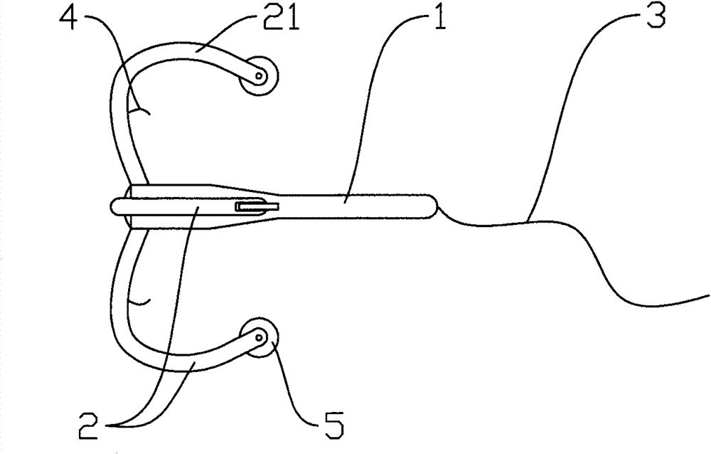
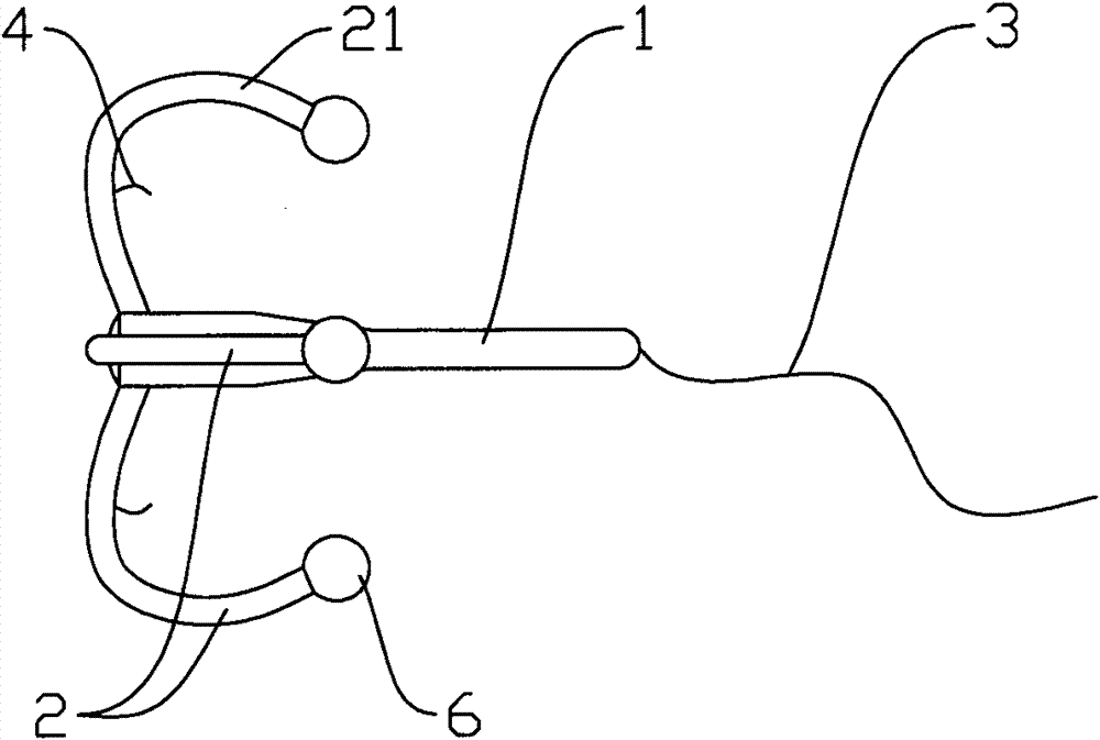
[0015] Such as figure 2 and 3 A structural schematic diagram of an embodiment of the present invention is shown, a quick mine removal tool, including an anchor rod 1, the front end of the anchor rod is a round blunt surface, and at least three backward-curved anchor hooks are arranged at the front end of the anchor rod 2. The present invention is provided with four anchor hooks, a pull rope 3 is provided at the rear end of the anchor rod, and a barb 4 for hooking a lightning trip wire is provided on the side of the middle part of the anchor hook corresponding to the rear end of the anchor rod, and the tail end of the anchor hook A smooth structure is provided to prevent the anchor hook from inserting into the soil or hooking the shrubs, and the smooth structure is a pulley 5 connected to the tail end of the anchor hook.

[0016] In the above-mentioned embodiment, the rear end of the anchor hook is set as the hook portion bent toward the anchor rod, and the distance between t...


PUM


Abstract

The invention discloses a tool for removing a tripmine quickly. The tool for removing the tripmine quickly comprises an anchor rod, wherein at least three anchor hooks bending backwards are arranged at the front end of the anchor rod; a digging rope is arranged at the rear end of the anchor rod; a barb for hooking a tripwire of the tripmine is arranged on one side of the middle part, corresponding to the rear end of the anchor rod, of each anchor hook; and a smooth structure for preventing the anchor hooks from being inserted into soil or hooking stones, weeds and shrubs is arranged at the tail end of each anchor hook. The tool for removing the tripmine quickly has a simple structure and is convenient to use; the tool is provided with the smooth structure, so that the anchor hooks can be prevented from being inserted into soil or hooking weeds or small shrubs in the process of retrieving the tool and the retrieving difficulty is reduced; the anchor rod is shot out by a crossbow or a spear gun, so the sliding distance of the anchor rod can be increased to 100 to 120 meters, namely, the mine-removing distance is increased, the mine-removing efficiency is improved and the safety of mine-removing operators is guaranteed.

Description

technical field [0001] The invention relates to a mine-sweeping tool, in particular to a quick mine-removing tool. Background technique [0002] If utilize artificially to search and get rid of the tripping mine that stays on the battlefield, not only inefficiency, but also have very big danger to demining personnel. Someone invented a tool for quickly removing trip mines in open areas, such as figure 1 As shown, it includes the hammer body 01, the rear end of the hammer body is provided with a handle 02, the rear end of the handle is connected with a drawstring 03, and the connection between the hammer body and the handle is provided with a barb 04 extending to the handle. Hold the handle and throw the hammer out, and the pull rope will be pulled out as the hammer slides in the air. After the hammer falls to the ground, the demining personnel will pull the rope to recover the hammer. During the recovery process, if the barb catches the hammer The trip wire of the mine wil...

Claims


Application Information

Patent Timeline
Patent Type & Authority Patents(China)
IPC IPC(8): F41H11/12
CPCF41H11/20
Inventor 徐彬
Owner 徐彬
Why Eureka
Try Eureka