Pneumatic variable pitch brake system of wind power generator

A wind turbine and brake system technology, applied in the control of wind turbines, wind turbines, wind power generation, etc., can solve the problems of long transmission distance, low service life, complex transmission mechanism, etc., to ensure the safety of power generation and the failure rate Reduced, direct effect of transmission force

Inactive Publication Date: 2012-07-04
QINGDAO MINSHEN WIND POWER TECH LIMITED
View PDF5 Cites 4 Cited by
  • Summary
  • Abstract
  • Description
  • Claims
  • Application Information

AI Technical Summary

Problems solved by technology

[0002] With the continuous development of the economy, people's demand for energy is increasing, and the reserves of non-renewable resources are seriously threatened. Therefore, people gradually turn their attention to renewable resources. As a clean and renewable energy, wind energy is becoming more and more important. The more and more countries in the world pay attention to it, which promotes the continuous innovation of wind turbines. The most important part of wind turbines is the wind blades that are directly in contact with wind energy and provide power for the generators. In order to better adapt to various wind directions, ensure The safety and service life of wind turbines. Most of the existing wind turbines control the blades through the hydraulic system. The hydraulic control system is easily affected by temperature and is not suitable for overcooling or overheating environments, and the service life is low. There are frequent failures such as oil leakage, which cannot guarantee the safety of wind turbines
The patent number is: 201020249951.X, and the patent name is: The invention patent of the wind turbine aerodynamic pitch braking system introduces a braking system that uses aerodynamic pitch to control the wind turbine, solving the problem of hydraulic braking. However, the above-mentioned patents have the disadvantages of complex transmission mechanism and long transmission distance

Method used


Image

  • Pneumatic variable pitch brake system of wind power generator
  • Pneumatic variable pitch brake system of wind power generator
  • Pneumatic variable pitch brake system of wind power generator

Examples


specific Embodiment 1

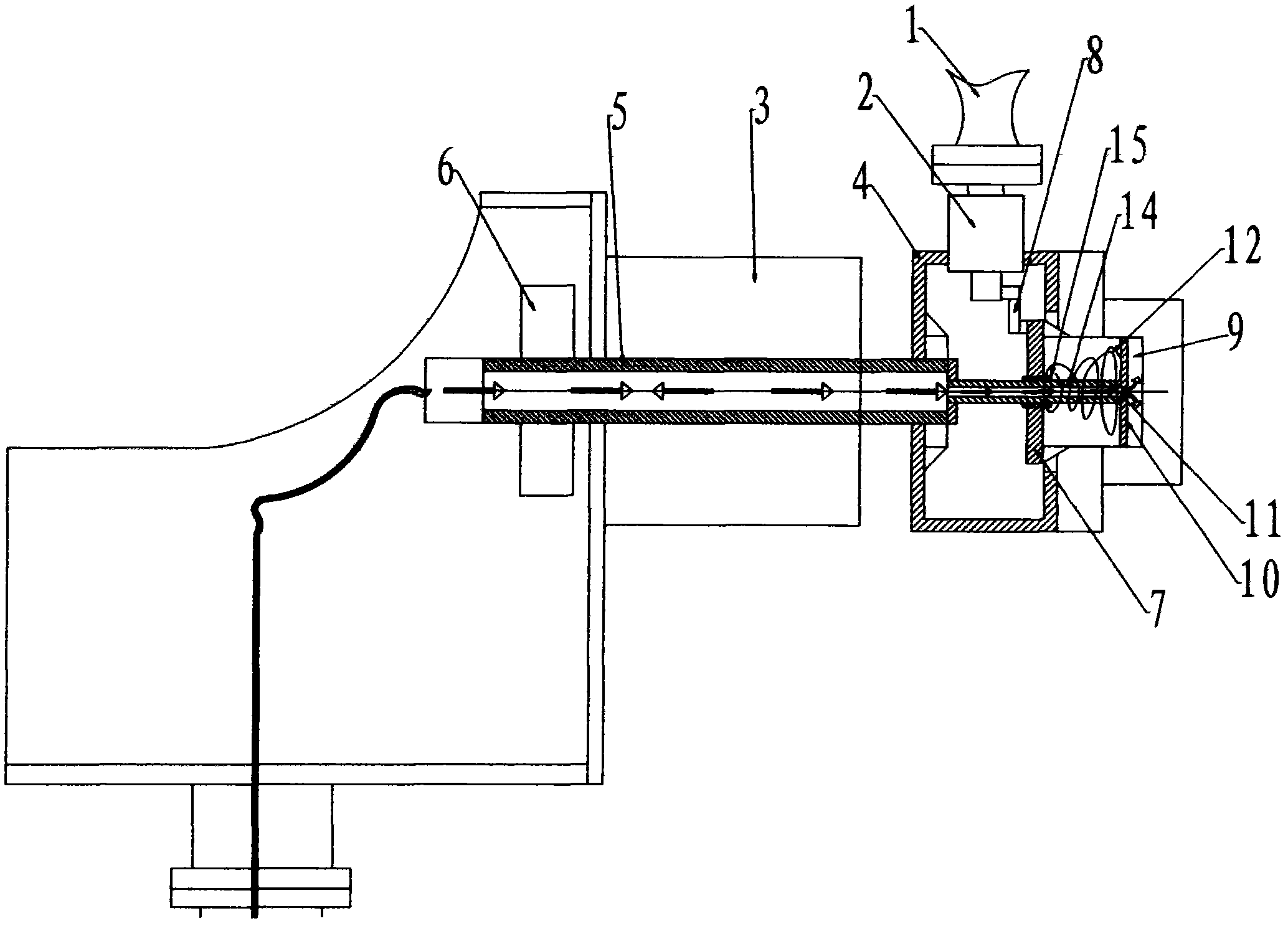
[0021] Specific embodiment 1: the synchronous disc drive mechanism includes a cylinder 9 fixedly mounted on the front end of the wheel hub 4, a piston 10 and a piston rod 11 are arranged inside the cylinder 9, and one end of the piston rod 11 protruding from the cylinder 9 is connected to the synchronous disc 7 , The piston rod 11 is sheathed with a return spring 12, and the flexible air pipe 13 of the cylinder 9 is connected to the pneumatic system through the rotor shaft 5. The piston rod 11 is provided with a spline 14, and the cylinder 9 is provided with a spline sleeve 15, which acts as a guide. The pneumatic pitch braking system is changed to the front type, the cylinder 9 is placed on the front end of the hub 4, and fixed on the hub 4. When inflating, the gas enters the cylinder 9 from the gas source through the soft air pipe 13, and the gas pushes the piston 10 and the piston rod 11 Push the synchronous disk 7 to move, change the angle of the fan blades, and realize th...

specific Embodiment 2

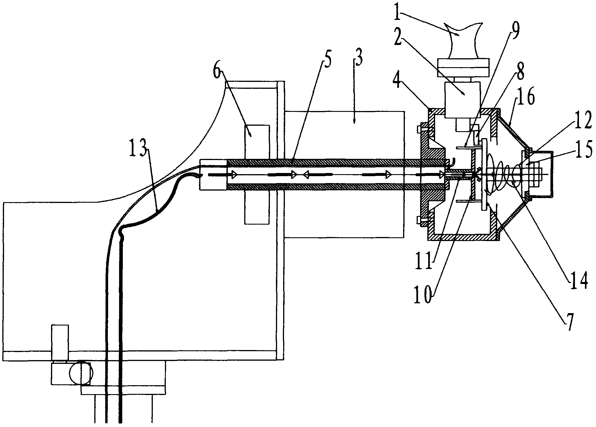
[0022] Specific embodiment 2: the described synchronous disk drive mechanism comprises the cylinder 9 that is installed on the synchronous disk 7, and the inside of the cylinder 9 is provided with a piston 10 and a piston rod 11, and one end of the piston rod 11 extending out of the cylinder 9 is fixed to the rotor shaft 5 Then, the outside of the piston rod 11 is covered with a return spring 12, and the inside of the rotor shaft 5 and the inside of the piston rod 11 are the air passages connected with the pneumatic system. The piston rod 11 is provided with a spline 14 , and the synchronous disc 7 is provided with a spline sleeve 15 . The pneumatic pitch system is changed to the front type, the cylinder 9 is placed at the front end of the wheel hub 4, and the cylinder 9 is fixed on the synchronous disc 7. When inflating, the gas enters the cylinder 9 from the air source through the soft air pipe 13. Since the piston 10 is fixed, the gas pushes the cylinder 9 moves to drive th...

specific Embodiment 3

[0023] Specific embodiment 3: The described synchronous disc drive mechanism includes a piston rod 11 and a piston 10 fixed on the rotor shaft 5, a cylinder 9 is arranged outside the piston 10, the cylinder wall is a synchronous disc 7, and the other end of the synchronous disc 7 is A reset device is provided. The resetting device includes a support base 16 installed on the hub, a spline sleeve 15 located on the support base 16, the spline sleeve 15 cooperates with the spline 14, and one end of the spline 14 is fixed on the synchronous disc 7, and the spline sleeve 15 cooperates with the spline 14. A back-moving spring 12 is sheathed on the outside of the key 14 . The pneumatic pitch system is changed to the front type, the cylinder 9 is placed on the front end of the hub 4, the cylinder 9 is fixed on the synchronous disk 7, the return spring 12 is placed outside the cylinder 9, and the front end of the rotor shaft 5 protrudes, which is equivalent to the piston rod 11, and the...


PUM


Abstract

The invention relates to a pneumatic variable pitch brake system of a wind power generator. Fan blades are rotatablely installed on a wheel hub of the wind power generator by a fan blade shaft, the wheel hub is connected with a rotor shaft, one side of the rotor shaft is provided with a disc type brake, the pneumatic variable pitch brake system is arranged at the front end of the wheel hub, and comprises a synchronous disc drive mechanism, a synchronous disc and a variable pitch connecting tumbler connected with the synchronous disc, and the variable pitch connecting tumbler is connected with the fan blade shaft of the fan blades, to drive fan blade variable pitch to be braked. The pneumatic variable pitch brake system is quick in reaction and is suitable for severe environments, is hardly influenced by environment, can be used in moist, dusty, vibratory and over-cold and over-hot environments, furthermore, a drive mechanism is simple in drive, and direct in driving force, so that the failure rate is greatly reduced, and power generation security of the wind power generator is guaranteed. When the pneumatic variable pitch brake system is aerated, the wind power generator normally works, and when the pneumatic variable pitch brake system is deflated, the wind power generator is braked or the variable pitch is performed, so that the wind power generator can be controlled without the sudden interruption or deflation, the variable pitch brake system can be manfully controlled or automatically controlled by a programmable logic controller (PLC), and the manual control is matched with the automatic control, and therefore, the wind power generator is safe and stable to work.

Description

technical field [0001] The invention relates to a wind blade speed control device of a wind generator, in particular to an aerodynamic pitch control system capable of controlling the wind blades of the wind generator to adjust or brake in an emergency according to the wind direction and wind force. Background technique [0002] With the continuous development of the economy, people's demand for energy is increasing, and the reserves of non-renewable resources are seriously threatened. Therefore, people gradually turn their attention to renewable resources. As a clean and renewable energy, wind energy is becoming more and more important. The more and more countries in the world pay attention to it, which promotes the continuous innovation of wind turbines. The most important part of wind turbines is the wind blades that are directly in contact with wind energy and provide power for the generators. In order to better adapt to various wind directions, ensure The safety and serv...

Claims


Application Information

Patent Timeline
IPC IPC(8): F03D7/04
CPCY02E10/723Y02E10/72
Inventor 姜春辉
Owner QINGDAO MINSHEN WIND POWER TECH LIMITED
Why Eureka
Try Eureka