
Double-shaft balance device of engine

An engine and shaft balancing technology, applied in inertia force compensation and other directions, can solve the problems of long balance shaft length, large space occupied by the balance shaft, and high cost, and achieve the effect of shortening the axial size and facilitating the layout of the whole machine.

Inactive Publication Date: 2012-07-04
ZHEJIANG GEELY AUTOMOBILE RES INST CO LTD +1
View PDF6 Cites 10 Cited by
  • Summary
  • Abstract
  • Description
  • Claims
  • Application Information

AI Technical Summary

Problems solved by technology

Although this technical solution adopts double balance shaft gear drive, which has the ability to eliminate periodic vibration, there are still certain defects
1. The length of the first balance shaft and the second balance shaft is basically the same as the crankshaft, so this arrangement also makes the balance shaft occupy a large space, making it difficult to arrange the whole machine
2. Two pairs of gear pairs are used for meshing transmission, that is, there are four gears, so there are problems such as high cost and easy noise.
3. The length of the balance shaft of the dual-axis balance device is long and there are many parts, resulting in a huge weight, which is contrary to the lightweight design concept of the engine
4. The structure of the first balance shaft and the second balance shaft is not the same, and they cannot be used in common use, which also leads to an increase in the cost of producing the engine

Method used


Image

  • Double-shaft balance device of engine
  • Double-shaft balance device of engine
  • Double-shaft balance device of engine

Examples


Embodiment Construction

[0029] The following are specific embodiments of the present invention in conjunction with the accompanying drawings to further describe the technical solutions of the present invention, but the present invention is not limited to these embodiments.

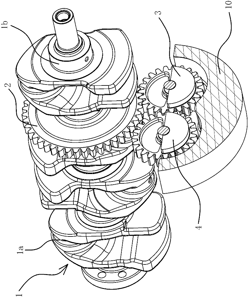
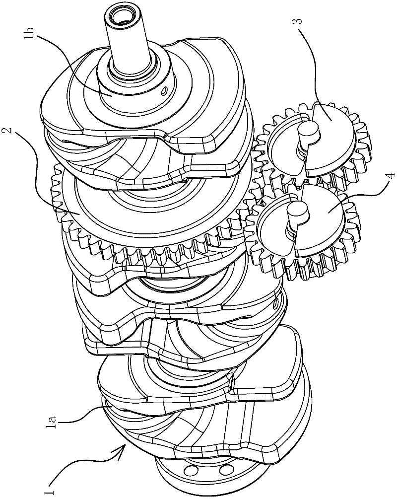
[0030] Such as figure 1 with figure 2 As shown, the engine includes a casing 10 and a crankshaft 1. The dual-axis balance device is arranged in the box body 10 and includes a driving gear 2, a first balance shaft 3 and a second balance shaft 4.

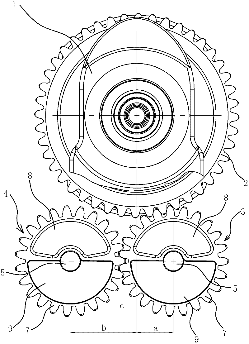
[0031] Specifically, such as figure 1 , figure 2 with image 3 As shown, the drive gear 2 is fixed on the crankshaft 1. The first balance shaft 3 and the second balance shaft 4 are arranged in parallel with respect to the main journal 1 b of the crankshaft 1 and located beside the crankshaft 1. The solution given in this embodiment is that the first balance shaft 3 and the second balance are located below the crankshaft 1; the first balance shaft 3 and the second balance are located on the...


PUM


Abstract

The invention provides a double-shaft balance device of an engine, which belongs to the technical field of mechanical engineering and resolves the technical problems of engine vibration and noise caused by vibration of the existing automobile. The double-shaft balance device of the engine comprises a driving gear fixed on a crank shaft and a first balance shaft and a second balance shaft which are arranged on the lateral side of the crank shaft and are parallel relative to a main journal of the crank shaft. The first balance shaft and the second balance shaft are respectively provided with a tooth portion, a shaft portion and a balance portion. The balance portion is arranged between the tooth portion and the shaft portion, and the weight of an area on one side of the balance portion relative to a radial line of the tooth portion is smaller than the weight of an area on the other side. The tooth portion of the first balance shaft is meshed with the tooth portion of the second balance shaft, and the tooth portion of the first balance shaft is meshed with the driving gear. The balance portion of the first balance shaft and the balance portion of the second balance shaft are symmetrically arranged relative to the meshing face of the first balance shaft and the second balance shaft. The double-shaft balance device facilitates integral machine arrangement and has the advantages of being compact in structure and small in size and saving cost.

Description

Technical field [0001] The invention belongs to the technical field of mechanical engineering, and relates to a shock absorption device, in particular to a biaxial balance device of an engine. Background technique [0002] Engine, also known as engine, is a machine that can convert other forms of energy into another kind of energy, usually chemical energy into mechanical energy. It is widely used in vehicles, ships and other equipment. [0003] With the rapid development of the automobile industry and the increasing requirements of people for automobile comfort, automobile engine vibration and the noise caused by vibration have become increasingly concerned issues in automobile engine design. [0004] The crank connecting rod mechanism is one of the important mechanisms of the engine. The reciprocating motion of the crank connecting rod mechanism of the engine will generate periodic reciprocating inertia force, thereby causing periodic vibration. In order to eliminate the above-men...

Claims


Application Information

Patent Timeline
Patent Type & Authority Applications(China)
IPC IPC(8): F16F15/26
Inventor 佟宇由毅沈源袁爽赵福全
Owner ZHEJIANG GEELY AUTOMOBILE RES INST CO LTD
Learn More